I don't think these descriptions are accurate, particularly the K2
versus K3 one.
The K2 is a fairly conventional, single conversion, analogue design. As
stated, it uses the crystal filter for primary selectivity. It
typically has up to two crystal filter options, one hard wired, and the
other as an integral part of the SSB adapter. The hard wired one is
adjustable, and the SSB one is fixed. The filters are constructed by
the final assembler, from individual crystals. Although there is a DSP
option, it works purely on the audio.
The K3 and K3X are software defined radios (SDRs) of the non-direct
sampling variety. I use SDR in the technical sense, not in the amateur
radio community sense; the latter requires the digital processing to be
performed on a PC. This means they have an analogue front end with at
least one analogue mixer, but the final processing is done digitally.
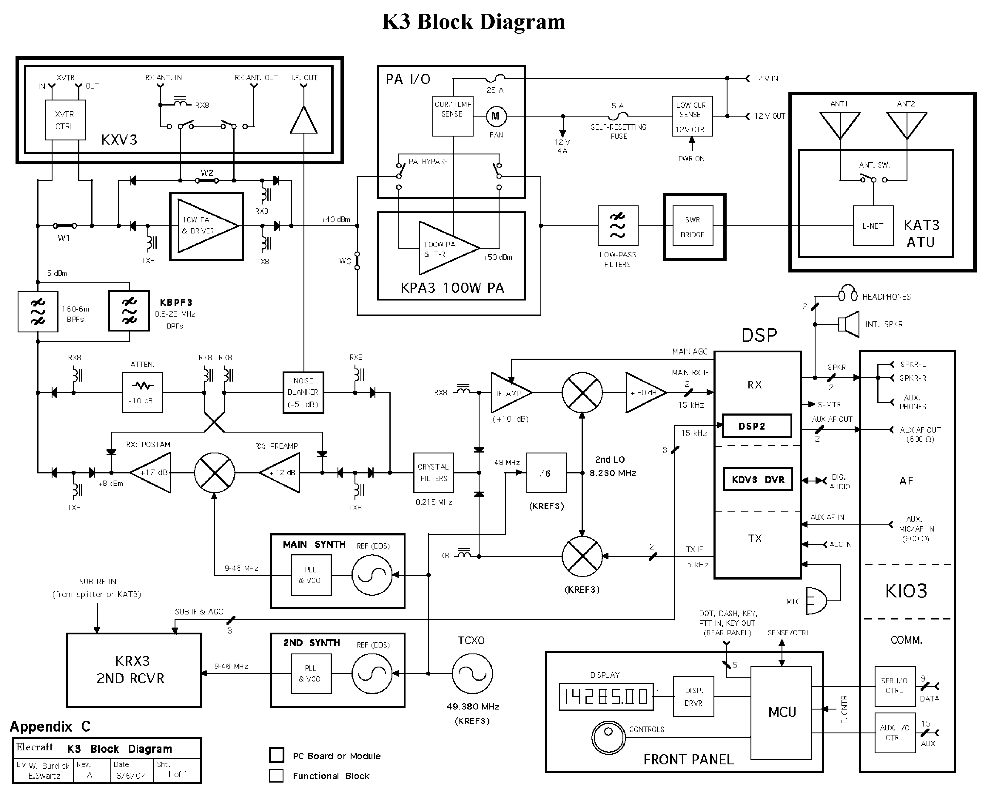
The K3 has a double conversion superhet architecture, with an HF first
IF and an extremely low second one. There is a selectable crystal
filter (using commercial sub-assemblies) in the first IF, which provides
coarse selectivity. The final IF processing is digital. There is a
quadrature path starting from the second mixer, analogue at that stage.
Combined with digital processing, this creates an analogue of a
phasing design receiver to suppress the final IF image, rather than the
audio image. As the signal continues in quadrature, the digital
processing may also act analogously to a phasing receiver to do the
final conversion and audio image stripping, but it may be that the
internal logic is more complex than that - the fine details are a trade
secret, although they may or may not have release information about that
part of it.
The K3 also does digital processing on the recovered audio, but this is
done within the same digital processor as the final IF processing.
The K3X, for CW at least, implements a hybrid analogue/SDR direct
conversion, phasing design. For SSB it may do the same, but it is also
possible that it actually implements a final passband centre at 0Hz, and
then does a final frequency shift to move the centre of the passband to
the correct audio frequency (i.e. they could have implemented it as a
single conversion architecture). Selectivity is provided entirely by
digital processing.
For both the K2 and K3, first mixer image rejection is provided by a
combination of band pass filters, optimised for each band, and a low
pass filter, also optimised for the band. For the KX3, the image is the
one removed by the phasing, although there is also analogue band and low
pass filtering - I'm not sure whether this is switched, or there is a
single, compromise, filter.
Block diagrams for all three are fairly easy to find. I have the K2, so
did that from memory, but the K3 one is at
<http://www.qsl.net/wb4kdi/Elecraft/K3/K3_Block.png> and the KX3 at
<http://www.elecraft.com/manual/KX3%20Manual%20Block%20Diagram.pdf>.
There are likely other places, including a better K3 image.
--
David Woolley
Owner K2 06123

On 11/12/15 21:40, Ron D'Eau Claire wrote:
The K3 and K2 and conventional superhetrodyne formats with an Intermediate
Frequency in the H.F. range and crystal filters to set the passband. The K2
has an adjustable crystal filter and the K3 uses fixed crystal filter
bandwidths. The basic K2 bandwidth is established by the crystal filter
while the K3 adds an adjustable DSP filter after the crystal filter. (The K2
has an optional audio DSP for enhanced filtering.)
______________________________________________________________
Elecraft mailing list
Home: http://mailman.qth.net/mailman/listinfo/elecraft
Help: http://mailman.qth.net/mmfaq.htm
Post: mailto:[email protected]

This list hosted by: http://www.qsl.net
Please help support this email list: http://www.qsl.net/donate.html
Message delivered to [email protected]