Just go back on this subject to older postings from Todd where he posted the
FreeCAD files.  I then used those to create step files and loaded them into
AlibreCAD.  Since then I've figured out how to make gears in AlibreCAD which
had a Python Script that used diameter and # of teeth.  I modified the script
to use module or diameter.
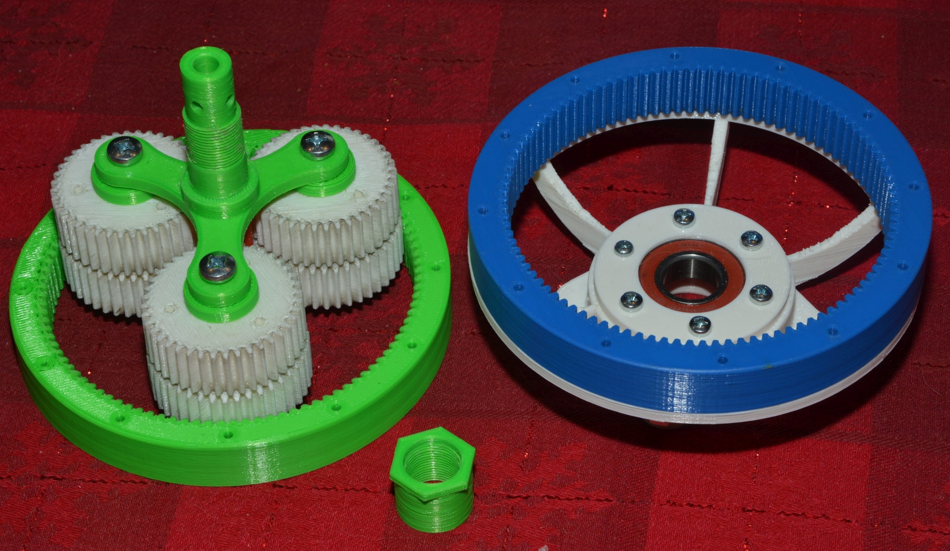
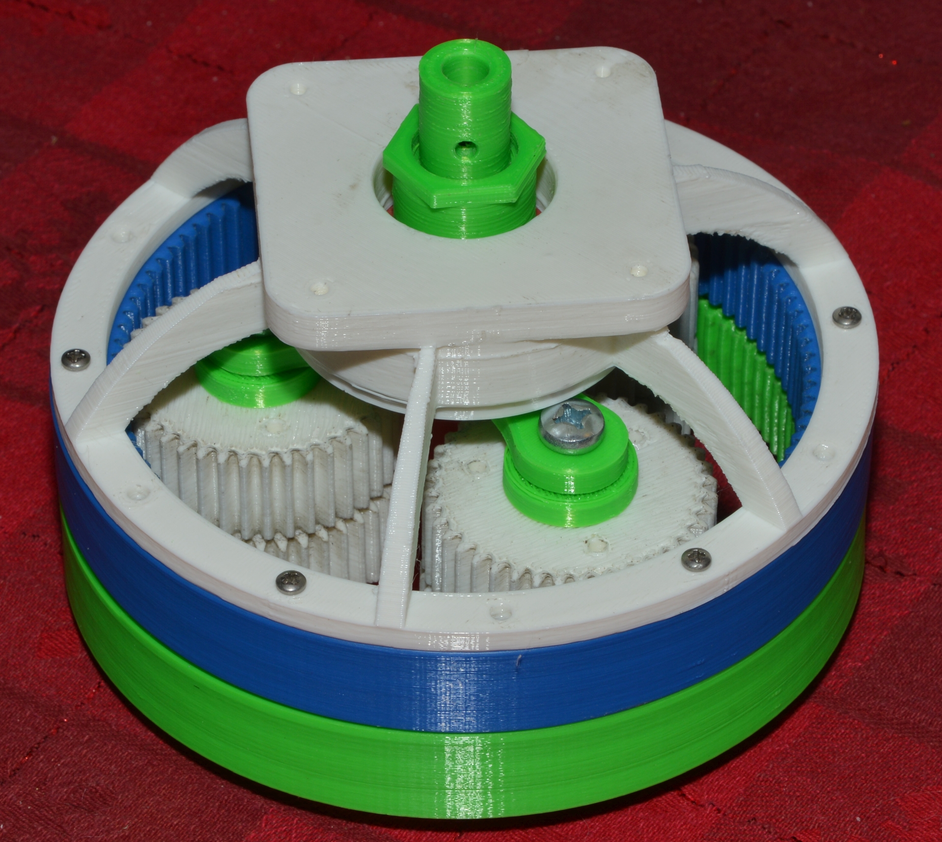
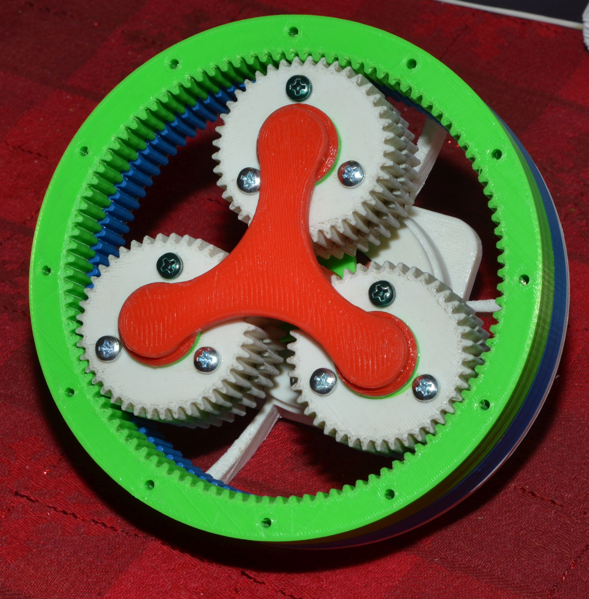
To create the ring gear I first create a normal gear with the right number of
teeth, module and thickness and save that.  Then create a disk with the desired
outside diameter and same thickness.  Then use a Boolean subtract with the gear
file.  That creates the ring gear with say 60mm OD and either 100T or 101T.

The spur gears are created separately as a 40T and 41T with the same size
center hole and three holes to connect the two so that at one point a pair of
teeth line up perfectly.   An assembly is made from those two with
constrictions to line them up.

Then an assembly of the entire set is done.  As yet I'm not clever enough to
make the assembly constraints simulate the entire planet assembly moving around
the ring gear.  And the reference lines I put on mine don't actually line up
with the correct teeth for assembly.  But I whipped that all up in under an
hour.

Todd mentioned in a private email how the ratios work.
" It is because it isn't behaving quite like a normal compound planetary.
Because the planets of each set are fixed to each other, when the planets sets
orbited around the fixed ring by the carrier, the driven ring gear is advanced
by (and this is the key) the difference between the two ratios.  The result is
when you turn the carrier one revolution, the planets of the fixed ring gear
turn 2.5 revolutions, therefore the driven ring's planets also turn 2.5
revolutions, since the ratio of the output set of gears is 2.4634, the ring is
advanced the difference of the two ratios. So the final drive math is [101/41]
/ [(100/40)-(101/41)].  Or 2.4634/(2.5-2.4634) = approx. 67.3.  "

It's actually 67.333...   If you want to get fussy.
Here's my 3D printed version of the 150mm diameter gears.
http://www.autoartisans.com/harmonicdrive/BearingDriveShaft-1.jpg
http://www.autoartisans.com/harmonicdrive/BearingDriveShaft-2.jpg
http://www.autoartisans.com/harmonicdrive/BearingDriveShaft-3.jpg

The bearing holds the drive centered and when the 3 planets are properly
aligned requires very little torque to move the non-fixed ring gear.  However I
have not yet come up with an inexpensive way to hold that gear in a way that it
would be useful.  I've been playing with a deep groove in the ring gear and a
holder outside that along with 80 of 5.5mm bearings.  And a bearing thrust
washer is also needed.

But the above example doesn't have bearings inside the planets either so it's
plastic on plastic.  I can provide the step files if you wish.

John


> -----Original Message-----
> From: grumpy via Emc-users [mailto:emc-users@lists.sourceforge.net]
> Sent: January-03-22 4:44 AM
> To: Enhanced Machine Controller (EMC)
> Cc: grumpy
> Subject: Re: [Emc-users] Harmonic Drive
>
> January 3, 2022 9:54:10 AM CET John Dammeyer <jo...@autoartisans.com> wrote:
> For fun I created Todd's version with 0.5module gears.  The OD of the assembly
> is now 60mm compared to 150mm.   It would now be possible to choose a far east
> harmonic drive tapered roller assembly to hold the driven gear in place.
> Although they are expensive.
>
> Not sure what type of bearings, if any would be used for the planetary gear
> clusters.  I suppose one could press in bronze sleeves.  I guess it all
> depends
> on the duty cycle and target application.  If it's a 6 axis robot arm used for
> tool changing and placement/removal of milled parts then it's not running
> continuously.  Might well for the home or small shop be more than adequate.
>
> This example still has 67.3333333:1 reduction but if the fit is well set then
> the backlash is essentially zero which is different from normal planetary
> reduction drives.   Not sure how important that is for a 6 axis robot arm.
>
> In either case, using a 4th axis to create all three spur gears at the same
> time (one set of 40T and one set of 41 T) and then some sort of
> broaching/indexing to create the two ring gears the real issue is the outer
> bearing of the 101T output ring gear.  But overall not that difficult to
> create
> once you have the 0.5 module shaper style cutter.
>
> John
>
> Where can I find more info about Todd's planetary drive.
> It looks very familiar.
> _______________________________________________
> Emc-users mailing list
> Emc-users@lists.sourceforge.net
> https://lists.sourceforge.net/lists/listinfo/emc-users


_______________________________________________
Emc-users mailing list
Emc-users@lists.sourceforge.net
https://lists.sourceforge.net/lists/listinfo/emc-users