                            EV Digest 2625

Topics covered in this issue include:
  1) Re: DCP controllers, update
        by Rich Rudman <[EMAIL PROTECTED]>
  2) Re: Thinking Wife almost made it home. Long
        by Peter VanDerWal <[EMAIL PROTECTED]>
  3) EV parts for sale
        by Joseph Vaughn-Perling <[EMAIL PROTECTED]>
  4) How AC Propulsion got there.
        by "Lawrence Rhodes" <[EMAIL PROTECTED]>
  5) ES CityCat.  Too good to be true?
        by "Lawrence Rhodes" <[EMAIL PROTECTED]>
  6) Re: Hot Rod Badsey HotScoot for sale on Ebay/Hot Tiwanese scooters.
        by "Lawrence Rhodes" <[EMAIL PROTECTED]>
  7) RE: Hot Rod Badsey HotScoot for sale on Ebay
        by Gordon Niessen <[EMAIL PROTECTED]>
  8) Fwd: [sparrow_ev] Sparrow #78 now on EBay
        by "John G. Lussmyer" <[EMAIL PROTECTED]>
  9) Re: Fwd: [sparrow_ev] Sparrow #78 now on EBay
        by [EMAIL PROTECTED]
 10) Re: Fwd: [sparrow_ev] Sparrow #78 now on EBay
        by "John G. Lussmyer" <[EMAIL PROTECTED]>
 11) RE: Hot Rod Badsey HotScoot for sale on Ebay
        by "Roy LeMeur" <[EMAIL PROTECTED]>
 12) Re: SVR batteries 4 sale
        by Steven Ciciora <[EMAIL PROTECTED]>
 13) Re: EV parts for sale
        by [EMAIL PROTECTED]
 14) Re: Hot Rod Badsey HotScoot for sale on Ebay/Hot Tiwanese scooters
        by "Roy LeMeur" <[EMAIL PROTECTED]>
 15) Re: Fwd: [sparrow_ev] Sparrow #78 now on EBay
        by Peter VanDerWal <[EMAIL PROTECTED]>
 16) Re: 6 Volt Battery Balancer?
        by Lee Hart <[EMAIL PROTECTED]>
 17) Re: DCP controllers, update
        by Lee Hart <[EMAIL PROTECTED]>
 18) re: BMS Communication
        by fred whitridge <[EMAIL PROTECTED]>
 19) Re: DCP controllers, update-GE Shunt control
        by Rod Hower <[EMAIL PROTECTED]>
 20) GE shunt control and motor information
        by Rod Hower <[EMAIL PROTECTED]>
 21) Voltmeter and shunt for sale
        by Bob Bath <[EMAIL PROTECTED]>
 22) Re: DCP controllers, update
        by [EMAIL PROTECTED]
 23) Re: DCP controllers, update-GE Shunt control
        by [EMAIL PROTECTED]
--- Begin Message ---
[EMAIL PROTECTED] wrote:
>
> Hi Rod,
> I originally purchased this motor to provide regenerative braking energy
> to the battery pack.   It is a standard GE Shunt Wound Motor with a
> weight of about 150 pounds, approximately  9 inch diameter and 16 inches
> long

Let me make it clear DCP does NOT have a Sepex controller ready for the
market.

AND Just plain forget about using Genaric Sepex motors on any Sepex
controller.

The motor and controller have to be designed as a unit and tested and
programmed.

It's like saying Can I hook any automatic Tranny up to my 86 2.3 liter
turbo???
Way too many specifics about both items.


Rich Rudman
Manzanita Micro
www.manzanitamicro.com
1-360-297-7383,Cell 1-360-620-6266
--- End Message ---
--- Begin Message ---
Did something like that as a kid.  Pounding in fence posts for a new
chicken run, my brother comes over and says "Hey, I stopped pounding on
this post a couple minutes ago and it's still vibrating" I go over and
feel the post and sure enough it's still vibrating, only..."Hey, that's
not vibration, that's electricity."  Turns out we hit the 220 power
lines going to the lower pump house (200 yards away).  Good job there
was a foot of post grounding it out before it got up to us.

> Its about the shocking shower stall. The Power Co. transformer had
> managed to engage on a city
> drain pipe that would give you that tingling feeling with the zest soap.
> True story.
> I have a few more now.
> Danny...
>
--
EVDL
--- End Message ---
--- Begin Message ---
Listed here:
http://www.socalev.com/for_sale.htm

A Rusco charger
and a DC/DC converter for up to 128V/12V

50% off of list price.

--
      ____
   __/o|__\~ ~ ~
  `@ [EMAIL PROTECTED](=
http://www.SoCalEV.com
--- End Message ---
--- Begin Message ---
It is amazing what AC Propulsion has achieved in the past with their
drivetrain.  I like the 145 mile part.  Wonder if this is the Honda or the
Tzero.  Lawrence Rhodes..
http://www.acpropulsion.com/Press%20releases/AC150%20two%20years.htm
--- End Message ---
--- Begin Message ---
Anyone know about this vehicle?  Lawrence Rhodes.....

The ES CityCat electric scooter, being developed by Schiller GmbH of
Germany, will enter the market in 2002. The 209 lb scooter has a range of 60
miles, lead acid batteries, and a limited top speed of 35 mph. It uses
patented high performance brushed and brushless motors and the latest
drivetrains and electronics and has a 15 minute fast charge (80% depth of
discharge). Optional Li-lon batteries. Other specs are comparable to 50 cc
gasoline scooters. The price $2,500. [EMAIL PROTECTED]
--- End Message ---
--- Begin Message ---
Chinese scooters might be what you need.  One had a 372 pound weight
capacity.  http://www.evfinder.com/twowheel.htm  They seemed to climb hills
well and have good range.  Maybe this is what you need.  Anyone got the 1700
buck Morad 1500 or simular scooters from Taiwan?  What are your impressions?
JC Penny seems to be out of them now.  Lawrence Rhodes......
----- Original Message -----
From: "James Jarrett" <[EMAIL PROTECTED]>
To: <[EMAIL PROTECTED]>
Sent: Friday, February 28, 2003 5:14 AM
Subject: RE: Hot Rod Badsey HotScoot for sale on Ebay


> Hey Roy,
>
> Besides snapping my neck and perhaps breaking a leg (minor annoyances in
the
> pursuit of speed)  do you have any idea what kind of RANGE this thing
would
> get with a 300 lb operator that kept it down to a "reasonable" speed?
>
> Thanks
>
> James
>
> James F. Jarrett
> Information Systems Associate
> Charlotte Country Day School
> (704)943-4562
>
> Beware of programmers who carry screwdrivers. - Leonard Brandwein
>
>
> -----Original Message-----
> From: [EMAIL PROTECTED] [mailto:[EMAIL PROTECTED]
> Behalf Of Roy LeMeur
> Sent: Friday, February 28, 2003 1:27 AM
> To: [EMAIL PROTECTED]
> Subject: Re: Hot Rod Badsey HotScoot for sale on Ebay
>
>
> Dang it! I forgot to put the URL in there, sorry!
>
> http://cgi.ebay.com/ws/eBayISAPI.dll?ViewItem&item=3118601776
>
>
>
> Roy LeMeur  Seattle WA
>
> My Electric Vehicle Pages:
> http://www.angelfire.com/ca4/renewables/evpage.html
>
> Informational Electric Vehicle Links:
> http://www.angelfire.com/ca4/renewables/evlinks.html
>
>
>
>
> _________________________________________________________________
> STOP MORE SPAM with the new MSN 8 and get 2 months FREE*
> http://join.msn.com/?page=features/junkmail
>
--- End Message ---
--- Begin Message ---
Interesting that you listed it as a "Toys & Hobbies:Electronic, Battery,
Wind-Up:Battery Operated:Modern (1970-Now)" rather then "Sports:Sporting
Goods:Scooters:Electric" like all the rest.
The URL again for those who might have missed it because I forgot to put
it in the first posting:
http://cgi.ebay.com/ws/eBayISAPI.dll?ViewItem&item=3118601776
Roy LeMeur Seattle WA
My Electric Vehicle Pages:
http://www.angelfire.com/ca4/renewables/evpage.html
Informational Electric Vehicle Links:
http://www.angelfire.com/ca4/renewables/evlinks.html
_________________________________________________________________
Tired of spam? Get advanced junk mail protection with MSN 8.
http://join.msn.com/?page=features/junkmail
--- End Message ---
--- Begin Message ---
Thought someone might be interested....
(There has been a rash of Sparrows for sale recently....)
Minimum bid is $6000. Thanks for looking!
http://cgi.ebay.com/ebaymotors/ws/eBayISAPI.dll?ViewItem&item=2405702612
--
John G. Lussmyer      mailto:[EMAIL PROTECTED]
Dragons soar and Tigers prowl while I dream....         http://www.CasaDelGato.com
--- End Message ---
--- Begin Message ---
I wonder why ?
Has anyone done a survey as to why they are for sale ?

On Sat, 01 Mar 2003 08:16:38 -0800 "John G. Lussmyer"
<[EMAIL PROTECTED]> writes:
> Thought someone might be interested....
> (There has been a rash of Sparrows for sale recently....)
>
> >Minimum bid is $6000.  Thanks for looking!
> >
>
>http://cgi.ebay.com/ebaymotors/ws/eBayISAPI.dll?ViewItem&item=2405702612
>
> --
> John G. Lussmyer      mailto:[EMAIL PROTECTED]
> Dragons soar and Tigers prowl while I
> dream....             http://www.CasaDelGato.com
>
>


________________________________________________________________
Sign Up for Juno Platinum Internet Access Today
Only $9.95 per month!
Visit www.juno.com
--- End Message ---
--- Begin Message ---
I know that several of them got jobs too far from home to let them use the
Sparrow.
I'm not using mine since it doesn't have the range to get to work
anymore. (I don't count the 1 mile round trip per week to check the PO box
as "using it".) That's why I'm looking into using LiIon's in mine.
At 12:12 PM 3/1/2003 -0400, [EMAIL PROTECTED] wrote:
I wonder why ?
Has anyone done a survey as to why they are for sale ?
On Sat, 01 Mar 2003 08:16:38 -0800 "John G. Lussmyer"
<[EMAIL PROTECTED]> writes:
> Thought someone might be interested....
> (There has been a rash of Sparrows for sale recently....)
--
John G. Lussmyer      mailto:[EMAIL PROTECTED]
Dragons soar and Tigers prowl while I dream....         http://www.CasaDelGato.com
--- End Message ---
--- Begin Message ---
Gordon Niessen wrote:
---------------
Interesting that you listed it as a "Toys & Hobbies:Electronic, Battery,
Wind-Up:Battery Operated:Modern (1970-Now)" rather then "Sports:Sporting
Goods:Scooters:Electric" like all the rest.
The URL again for those who might have missed it because I forgot to put it
in the first posting:
http://cgi.ebay.com/ws/eBayISAPI.dll?ViewItem&item=3118601776
------------------------
Category changed to "Sports:Sporting Goods:Scooters:Electric"
Roy LeMeur Seattle WA
My Electric Vehicle Pages:
http://www.angelfire.com/ca4/renewables/evpage.html
Informational Electric Vehicle Links:
http://www.angelfire.com/ca4/renewables/evlinks.html
_________________________________________________________________
MSN 8 with e-mail virus protection service: 2 months FREE*
http://join.msn.com/?page=features/virus
--- End Message ---
--- Begin Message ---
You might want to consider advertising on some of the Battlebot forums.
These batteries go for about $80.  For example:

http://www.robotcombat.com/store_npcbatteries.html

So you are selling your SVRs, selling your nicads, it dosn't sound like
you want to run LiIon...  so what are you using, Suppercaps? :-)

- Steven Ciciora

>I have 100 svr14 batteries and 50 svr30 batteries 4 sale.They are brand
>new and have never been hooked up but have been on float for
>13months.svr14s $25ea. svr30s $35 Dennis Kilowatt Berube 6023777583
--- End Message ---
--- Begin Message ---
What are the specifications of a Sevcon 622 - 11 - 14 DC/DC onverter
other than 128vdc/121vdc ?
Only the model number was listed in the for sale area os socalev.
What is the wattage rating of the DC/DC converter ?
Is that converting up to 128 vdc down to 12 vdc ?
What is range for converting from (24 vdc to 128 vdc or some other range)
?
What is the actual output voltage (12, 12.5, 13, 13.5, 14, 14.5, etc) and
is it adjustable ?
Menlo Park III,
Bill

On Fri, 28 Feb 2003 20:49:34 -0800 (PST) Joseph Vaughn-Perling
<[EMAIL PROTECTED]> writes:
> Listed here:
> http://www.socalev.com/for_sale.htm
>
> A Rusco charger
> and a DC/DC converter for up to 128V/12V
>
> 50% off of list price.
>
> --
>       ____
>    __/o|__\~ ~ ~
>   `@ [EMAIL PROTECTED](=
> http://www.SoCalEV.com
>
>


________________________________________________________________
Sign Up for Juno Platinum Internet Access Today
Only $9.95 per month!
Visit www.juno.com
--- End Message ---
--- Begin Message ---
Lawrence Rhodes wrote:
--------------------
Anyone got the 1700
buck Morad 1500 or simular scooters from Taiwan? What are your impressions?
--------------------
Sheer has one and loves it.
Roderick and I both have lots of saddle time on them.
Tom True and the Silver Bullet crew have two, they like them.
This would actually be a good choice for a heavier rider though certainly
not a board scooter :-)
Super silent, climbs hills very well.
Battery weight is a little high in the chassis but you get used to it.
Scooter weighs about 300 lbs.
Controller provides an very soft start from rest, I suspect that this is to
protect the hubmotor from over current damage at zero RPM.
Once you start rolling, the power comes on smoothly and it provides plenty
of it.
Suspension and brakes are very good, nice body work and finish especially
for a Chinese scooter.
Advertised range is 30-40 miles, more like 25 in the real world.
NEDRA record holder!
Roderick's idea, there was no record in that class, he put his "girlfriend
of the moment" on one and she became a NEDRA record holder. :^D
Class: SP/I
"Mo Rad Scooter" - 48V
Driver: Quija Keogh
Owner: EV Parts
1/8 mile/seconds: 18.494
MPH: 32.89
Woodburn Drags 2002
Battery pack was quite depleted when this run was made, top speed is
actually more like 35-37 mph with a light rider.
Roy LeMeur Seattle WA
My Electric Vehicle Pages:
http://www.angelfire.com/ca4/renewables/evpage.html
Informational Electric Vehicle Links:
http://www.angelfire.com/ca4/renewables/evlinks.html
_________________________________________________________________
The new MSN 8: smart spam protection and 2 months FREE*
http://join.msn.com/?page=features/junkmail
--- End Message ---
--- Begin Message ---
Probably the same reason most EVs o up for sale.  The batteries wore
out.

On Sat, 2003-03-01 at 09:12, [EMAIL PROTECTED] wrote:
> I wonder why ?
> Has anyone done a survey as to why they are for sale ?
>
> On Sat, 01 Mar 2003 08:16:38 -0800 "John G. Lussmyer"
> <[EMAIL PROTECTED]> writes:
> > Thought someone might be interested....
> > (There has been a rash of Sparrows for sale recently....)
> >
> > >Minimum bid is $6000.  Thanks for looking!
> > >
> >
> >http://cgi.ebay.com/ebaymotors/ws/eBayISAPI.dll?ViewItem&item=2405702612
> >
> > --
> > John G. Lussmyer      mailto:[EMAIL PROTECTED]
> > Dragons soar and Tigers prowl while I
> > dream....           http://www.CasaDelGato.com
> >
> >
>
>
> ________________________________________________________________
> Sign Up for Juno Platinum Internet Access Today
> Only $9.95 per month!
> Visit www.juno.com
>
--
EVDL
--- End Message ---
--- Begin Message ---
>> the problem is that the BatMod series has a hole in its range
>> of input voltages.

David Roden wrote:
> Use two 36v nominal DC/DCs, one for each half of the pack.

I did this in my old ComutaVan; I had two 36vdc input, 12vdc output
Vicors. The outputs were in parallel, and the inputs were powered from
different halves of the 72v pack. But, there was nothing to enforce
equal load sharing btween the two DC/DCs. In fact, with both DC/DCs
delivering the same output power, the higher-voltage half-pack actually
supplied less current than the lower-voltage half-pack.

But this worked out fine because the ComutaVan had a 36v/72v contactor
controller. Half the time, the two half-packs were in parallel, and
tended to self-balance the charge between them.
--
Lee A. Hart                Ring the bells that still can ring
814 8th Ave. N.            Forget your perfect offering
Sartell, MN 56377 USA      There is a crack in everything
leeahart_at_earthlink.net  That's how the light gets in - Leonard Cohen
--- End Message ---
--- Begin Message ---
[EMAIL PROTECTED] wrote:
> It is a standard GE Shunt Wound Motor with a weight of about 150
> pounds, approximately 9 inch diameter and 16 inches long. The name
> plate simply states: 96 vdc, 250 amp DC Shunt Wound Motor, but the
> engineer at GE said that the shunt winding must never see more
> than 36 volts DC or it will draw 20 amps and instantly fry the
> shunt windings.

"36v at 20 amps will fry the winding" is not very useful information. It
tells us what will destroy it, but not what the CORRECT voltage should
be.

At most, it implies that the field winding resistance is R = 36v / 20a =
1.8 ohms, which you could have found out for yourself with an ohmmeter.

If it really is 1.8 ohms, then a rough guess is that field power is
about 1% of armature power. 96v at 250a = 24,000w so field power is
240w. That is about 20.8v at 11.5a.

Lacking any real specifications, you can test the power rating of the
shunt winding for yourself. You'll need an adjustable DC power supply
(or string of batteries), a good digital ohmmeter, and a DPDT switch
good for the field current and voltage involved. Wire it up so the field
winding can be switched to the DC power supply or to the ohmmeter.

What you need to do is measure the field winding resistance cold, then
power the field so it heats up, then measure the field resistance hot.
Since we know it is wound with copper wire, and we know the temperature
coefficient for copper, the resistance change tells us the winding
temperature.

We then can compare this with the motor's maximum temperature class
rating to see if that voltage is too high. See if the nameplate gives
the insulation "class" rating. It will either be a letter code or a
number code ("class B" or "class 130"). If you don't have any
information to the contrary, assume it is class 130. Here are the most
common codes:

 Class     max temperature
--------   ---------------
A or 105   105 deg.C
B or 130   130 deg.C
F or 155   155 deg.C
H or 180   180 deg.C

Here is the formula to convert resistance into temperature rise:

Thot = ((Rhot-Rcold)/Rhot) x 256.4 + Tcold

where Rhot is the hot resistance in ohms
      Rcold is the cold resistance in ohms
      Thot is the hot temperature in degrees C
      Tcold is the cold temperature in degrees C
      256.4 is the resistance vs. temperature coefficient of copper

So, measure the field resistance cold (Rcold). Start by applying a low
voltage to the field, and every few minutes or so, flip the switch and
quickly measure the field resistance at its current temperature (Rhot).
Calculate its hot temperature (Thot).

It takes a long time for the temperature to stop rising. At low field
voltages, it takes an hour or more to stop rising, and even then it will
never reach 130 deg.C. At higher voltages, it takes less and less time
to reach 130 deg.C. So, your data will look sort of like this:

field    max temp.   time to reach
voltage  after 1 hr  130 deg.C
-------  ----------  -------------
 6v       50 deg.C   never
12v      100 deg.C   2 hours
18v      130 deg.C   1 hour
24v                  10 minutes
30v                  1 minutes
36v                  5 seconds

> This $2300 motor self destructed during the 1996 American Tour de Sol
> and took my $1000 PMC 96 volt Transistorized Pulse Width Modulated
> Controller along with it to the electronics grave yard.

What exactly failed in the motor? Do you know whether the motor failed
and took out the controller, or did the controller fail and take out the
motor?

One problem with a shunt motor is that you need a system that guarantees
you have field current before armature power is applied. If (for
example), the field wire falls off while you are driving down the road
and nothing senses the lack of field current, the motor will indeed
start smoking and emitting sparks, and will rapidly destroy the armature
controller.

> I have not had the opportunity to use the new motor as I don't have
> a suitable controller or control system for it. I guess I could use
> four 8 volt batteries in series to provide 32 volts nominal with a
> simple on/off relay connected to the ignition key and use a standard
> PWM controller for the armature

This would work; it would behave like a PM motor. But of course you need
to be sure that the field really can take 32 volts continuously. And,
the PWM controller you use on the armature should be able to operate
without a series field's inductance (you might have to add your own
series inductor).

But, the whole point of a shunt motor is NOT to run it with a continuous
fixed field current. You change the field current to control its speed.
To use this motor properly, you want to have TWO controllers; one for
the armature, and one for the field. The armature controller can be a
plain old Curtis PWM (possibly with an inductor in series so its current
limit works properly). The field controller can be another small PWM, or
just a rheostat in series with the pack.

The two controllers should be coordinated to give you the desired
torque-speed characteristics. The crudest way is to connect both
controller's pot boxes to the accellerator pedal so that they go in
opposite directions (MAX field voltage at MIN armature voltage, MIN
field voltage at MAX armature voltage). The pedal response is sort of
like this (I'll assume "full field" is 20v):

pedal position  field voltage   armature voltage
--------------  -------------  -------------------
fully released  20v (full)     0v (0% duty cycle)
1/4             full           48v (50% duty cycle)
1/2             full           96v (100% duty cycle)
3/4             10v (half)     96v
fully pressed   5v (1/4th)     96v

Notice that you keep it at full field until the armature controller is
fully on; then you keep the armature fully on as you reduce the field
strength.

Also note that if you fully release the throttle at speed, you will get
LARGE amounts of regen current. Curtis controllers cannot control regen
current. You will have to somehow limit this current or are liable to
burn something up.
--
Lee A. Hart                Ring the bells that still can ring
814 8th Ave. N.            Forget your perfect offering
Sartell, MN 56377 USA      There is a crack in everything
leeahart_at_earthlink.net  That's how the light gets in - Leonard Cohen
--- End Message ---
--- Begin Message ---
* LP8.2: HTML/Attachments detected, removed from message *
--- End Message ---
--- Begin Message ---
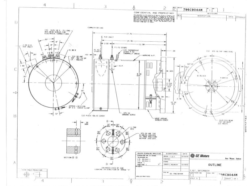
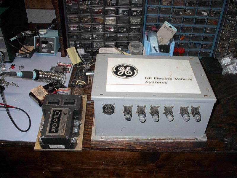
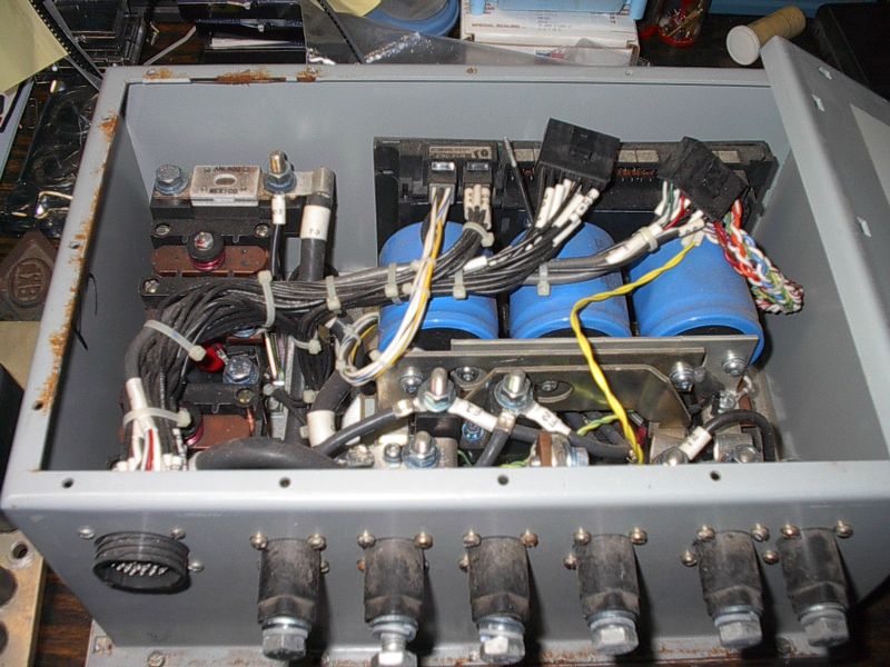
Hopefully I will have a picture of the GE control on my website sometime
tommorow.
This is one that was designed by me based on the Chrysler TEVan control.
I also have speed torque curves for the 96V shunt motor along with field
winding current.
Send the nameplate information if you have it.
Rod.
Lee Hart wrote:
[EMAIL PROTECTED] wrote:
It is a standard GE Shunt Wound Motor with a weight of about 150
pounds, approximately 9 inch diameter and 16 inches long. The name
plate simply states: 96 vdc, 250 amp DC Shunt Wound Motor, but the
engineer at GE said that the shunt winding must never see more
than 36 volts DC or it will draw 20 amps and instantly fry the
shunt windings.
"36v at 20 amps will fry the winding" is not very useful information. It
tells us what will destroy it, but not what the CORRECT voltage should
be.
At most, it implies that the field winding resistance is R = 36v / 20a =
1.8 ohms, which you could have found out for yourself with an ohmmeter.
If it really is 1.8 ohms, then a rough guess is that field power is
about 1% of armature power. 96v at 250a = 24,000w so field power is
240w. That is about 20.8v at 11.5a.
Lacking any real specifications, you can test the power rating of the
shunt winding for yourself. You'll need an adjustable DC power supply
(or string of batteries), a good digital ohmmeter, and a DPDT switch
good for the field current and voltage involved. Wire it up so the field
winding can be switched to the DC power supply or to the ohmmeter.
What you need to do is measure the field winding resistance cold, then
power the field so it heats up, then measure the field resistance hot.
Since we know it is wound with copper wire, and we know the temperature
coefficient for copper, the resistance change tells us the winding
temperature.
We then can compare this with the motor's maximum temperature class
rating to see if that voltage is too high. See if the nameplate gives
the insulation "class" rating. It will either be a letter code or a
number code ("class B" or "class 130"). If you don't have any
information to the contrary, assume it is class 130. Here are the most
common codes:
Class     max temperature
--------   ---------------
A or 105   105 deg.C
B or 130   130 deg.C
F or 155   155 deg.C
H or 180   180 deg.C
Here is the formula to convert resistance into temperature rise:
Thot = ((Rhot-Rcold)/Rhot) x 256.4 + Tcold
where Rhot is the hot resistance in ohms
     Rcold is the cold resistance in ohms
     Thot is the hot temperature in degrees C
     Tcold is the cold temperature in degrees C
     256.4 is the resistance vs. temperature coefficient of copper
So, measure the field resistance cold (Rcold). Start by applying a low
voltage to the field, and every few minutes or so, flip the switch and
quickly measure the field resistance at its current temperature (Rhot).
Calculate its hot temperature (Thot).
It takes a long time for the temperature to stop rising. At low field
voltages, it takes an hour or more to stop rising, and even then it will
never reach 130 deg.C. At higher voltages, it takes less and less time
to reach 130 deg.C. So, your data will look sort of like this:
field    max temp.   time to reach
voltage  after 1 hr  130 deg.C
-------  ----------  -------------
6v       50 deg.C   never
12v      100 deg.C   2 hours
18v      130 deg.C   1 hour
24v                  10 minutes
30v                  1 minutes
36v                  5 seconds
This $2300 motor self destructed during the 1996 American Tour de Sol
and took my $1000 PMC 96 volt Transistorized Pulse Width Modulated
Controller along with it to the electronics grave yard.
What exactly failed in the motor? Do you know whether the motor failed
and took out the controller, or did the controller fail and take out the
motor?
One problem with a shunt motor is that you need a system that guarantees
you have field current before armature power is applied. If (for
example), the field wire falls off while you are driving down the road
and nothing senses the lack of field current, the motor will indeed
start smoking and emitting sparks, and will rapidly destroy the armature
controller.
I have not had the opportunity to use the new motor as I don't have
a suitable controller or control system for it. I guess I could use
four 8 volt batteries in series to provide 32 volts nominal with a
simple on/off relay connected to the ignition key and use a standard
PWM controller for the armature
This would work; it would behave like a PM motor. But of course you need
to be sure that the field really can take 32 volts continuously. And,
the PWM controller you use on the armature should be able to operate
without a series field's inductance (you might have to add your own
series inductor).
But, the whole point of a shunt motor is NOT to run it with a continuous
fixed field current. You change the field current to control its speed.
To use this motor properly, you want to have TWO controllers; one for
the armature, and one for the field. The armature controller can be a
plain old Curtis PWM (possibly with an inductor in series so its current
limit works properly). The field controller can be another small PWM, or
just a rheostat in series with the pack.
The two controllers should be coordinated to give you the desired
torque-speed characteristics. The crudest way is to connect both
controller's pot boxes to the accellerator pedal so that they go in
opposite directions (MAX field voltage at MIN armature voltage, MIN
field voltage at MAX armature voltage). The pedal response is sort of
like this (I'll assume "full field" is 20v):
pedal position  field voltage   armature voltage
--------------  -------------  -------------------
fully released  20v (full)     0v (0% duty cycle)
1/4             full           48v (50% duty cycle)
1/2             full           96v (100% duty cycle)
3/4             10v (half)     96v
fully pressed   5v (1/4th)     96v
Notice that you keep it at full field until the armature controller is
fully on; then you keep the armature fully on as you reduce the field
strength.
Also note that if you fully release the throttle at speed, you will get
LARGE amounts of regen current. Curtis controllers cannot control regen
current. You will have to somehow limit this current or are liable to
burn something up.
--- End Message ---
--- Begin Message ---
I just posted the info to my web page.
http://www.qsl.net/w8rnh/B104mecs.jpg
http://www.qsl.net/w8rnh/B104shns.jpg
http://www.qsl.net/w8rnh/shntcnt2.jpg
http://www.qsl.net/w8rnh/shntctr1.jpg
Rod
--- End Message ---
--- Begin Message ---
Hey, while I clean house to get ready for Civic
conversion, there are a couple of old parts leftover
from Rabbit enhancements.  If anyone is interested,
here they are:
400A Shunt (I upped it to 500A)   $11
100V voltmeter; Westberg type, 2" dia mount.  $24

   If you check your catalogs, you'll find that these
items are exactly 1/2 of original price.  I figured
this is just slightly faster than the Trading Post--
but just _barely_ faster, Mike!   (;-p

__________________________________________________
Do you Yahoo!?
Yahoo! Tax Center - forms, calculators, tips, more
http://taxes.yahoo.com/
--- End Message ---
--- Begin Message ---
Hi Lee,
Ok, now for the series inductor.
The old 96 volt PMC Controller required a 100 uH series inductor for 400
amps and 4000 Hz audio hum.
Where could I get an inductor of that rating that would handle atleast
250 amps and not be extremely large, heavy, or expensive ???
Do you need to protect yourself from the electromagnetic field generated
from the inductor ?
Ok, now the old 96 volt PMC Controller is history, but I still can
operate up to a 108 volt battery pack with an old 72 volt PMC Controller,
a new Curtis 1231C, or even a new DCP Controller.     Will the same
series inductor work with any of these controllers (different frequency
controllers) for this GE motor ?????
Menlo Park III,
Bill
On Sat, 01 Mar 2003 14:28:24 -0800 Lee Hart <[EMAIL PROTECTED]>
writes:
> [EMAIL PROTECTED] wrote:
> > It is a standard GE Shunt Wound Motor with a weight of about 150
> > pounds, approximately 9 inch diameter and 16 inches long. The name
> > plate simply states: 96 vdc, 250 amp DC Shunt Wound Motor, but the
> > engineer at GE said that the shunt winding must never see more
> > than 36 volts DC or it will draw 20 amps and instantly fry the
> > shunt windings.
>
> "36v at 20 amps will fry the winding" is not very useful
> information. It
> tells us what will destroy it, but not what the CORRECT voltage
> should
> be.
>
> At most, it implies that the field winding resistance is R = 36v /
> 20a =
> 1.8 ohms, which you could have found out for yourself with an
> ohmmeter.
>
> If it really is 1.8 ohms, then a rough guess is that field power is
> about 1% of armature power. 96v at 250a = 24,000w so field power is
> 240w. That is about 20.8v at 11.5a.
>
> Lacking any real specifications, you can test the power rating of
> the
> shunt winding for yourself. You'll need an adjustable DC power
> supply
> (or string of batteries), a good digital ohmmeter, and a DPDT switch
> good for the field current and voltage involved. Wire it up so the
> field
> winding can be switched to the DC power supply or to the ohmmeter.
>
> What you need to do is measure the field winding resistance cold,
> then
> power the field so it heats up, then measure the field resistance
> hot.
> Since we know it is wound with copper wire, and we know the
> temperature
> coefficient for copper, the resistance change tells us the winding
> temperature.
>
> We then can compare this with the motor's maximum temperature class
> rating to see if that voltage is too high. See if the nameplate
> gives
> the insulation "class" rating. It will either be a letter code or a
> number code ("class B" or "class 130"). If you don't have any
> information to the contrary, assume it is class 130. Here are the
> most
> common codes:
>
>  Class     max temperature
> --------   ---------------
> A or 105   105 deg.C
> B or 130   130 deg.C
> F or 155   155 deg.C
> H or 180   180 deg.C
>
> Here is the formula to convert resistance into temperature rise:
>
> Thot = ((Rhot-Rcold)/Rhot) x 256.4 + Tcold
>
> where Rhot is the hot resistance in ohms
>       Rcold is the cold resistance in ohms
>       Thot is the hot temperature in degrees C
>       Tcold is the cold temperature in degrees C
>       256.4 is the resistance vs. temperature coefficient of copper
>
> So, measure the field resistance cold (Rcold). Start by applying a
> low
> voltage to the field, and every few minutes or so, flip the switch
> and
> quickly measure the field resistance at its current temperature
> (Rhot).
> Calculate its hot temperature (Thot).
>
> It takes a long time for the temperature to stop rising. At low
> field
> voltages, it takes an hour or more to stop rising, and even then it
> will
> never reach 130 deg.C. At higher voltages, it takes less and less
> time
> to reach 130 deg.C. So, your data will look sort of like this:
>
> field    max temp.   time to reach
> voltage  after 1 hr  130 deg.C
> -------  ----------  -------------
>  6v       50 deg.C   never
> 12v      100 deg.C   2 hours
> 18v      130 deg.C   1 hour
> 24v                  10 minutes
> 30v                  1 minutes
> 36v                  5 seconds
>
> > This $2300 motor self destructed during the 1996 American Tour de
> Sol
> > and took my $1000 PMC 96 volt Transistorized Pulse Width Modulated
> > Controller along with it to the electronics grave yard.
>
> What exactly failed in the motor? Do you know whether the motor
> failed
> and took out the controller, or did the controller fail and take out
> the
> motor?
>
> One problem with a shunt motor is that you need a system that
> guarantees
> you have field current before armature power is applied. If (for
> example), the field wire falls off while you are driving down the
> road
> and nothing senses the lack of field current, the motor will indeed
> start smoking and emitting sparks, and will rapidly destroy the
> armature
> controller.
>
> > I have not had the opportunity to use the new motor as I don't
> have
> > a suitable controller or control system for it. I guess I could
> use
> > four 8 volt batteries in series to provide 32 volts nominal with a
> > simple on/off relay connected to the ignition key and use a
> standard
> > PWM controller for the armature
>
> This would work; it would behave like a PM motor. But of course you
> need
> to be sure that the field really can take 32 volts continuously.
> And,
> the PWM controller you use on the armature should be able to operate
> without a series field's inductance (you might have to add your own
> series inductor).
>
> But, the whole point of a shunt motor is NOT to run it with a
> continuous
> fixed field current. You change the field current to control its
> speed.
> To use this motor properly, you want to have TWO controllers; one
> for
> the armature, and one for the field. The armature controller can be
> a
> plain old Curtis PWM (possibly with an inductor in series so its
> current
> limit works properly). The field controller can be another small
> PWM, or
> just a rheostat in series with the pack.
>
> The two controllers should be coordinated to give you the desired
> torque-speed characteristics. The crudest way is to connect both
> controller's pot boxes to the accellerator pedal so that they go in
> opposite directions (MAX field voltage at MIN armature voltage, MIN
> field voltage at MAX armature voltage). The pedal response is sort
> of
> like this (I'll assume "full field" is 20v):
>
> pedal position  field voltage   armature voltage
> --------------  -------------  -------------------
> fully released  20v (full)     0v (0% duty cycle)
> 1/4             full           48v (50% duty cycle)
> 1/2             full           96v (100% duty cycle)
> 3/4             10v (half)     96v
> fully pressed   5v (1/4th)     96v
>
> Notice that you keep it at full field until the armature controller
> is
> fully on; then you keep the armature fully on as you reduce the
> field
> strength.
>
> Also note that if you fully release the throttle at speed, you will
> get
> LARGE amounts of regen current. Curtis controllers cannot control
> regen
> current. You will have to somehow limit this current or are liable
> to
> burn something up.
> --
> Lee A. Hart                Ring the bells that still can ring
> 814 8th Ave. N.            Forget your perfect offering
> Sartell, MN 56377 USA      There is a crack in everything
> leeahart_at_earthlink.net  That's how the light gets in - Leonard
> Cohen
>
>


________________________________________________________________
Sign Up for Juno Platinum Internet Access Today
Only $9.95 per month!
Visit www.juno.com
--- End Message ---
--- Begin Message ---
Hi Rod,
I have a full set of power curves (armature verse shunt field, with RPM,
torque, etc.)  from GE for all shunt voltages from 5 volts up to 42 volts
for some unknown reason as the shunt windings will fry if they see 36
volts.
Menlo Park III,
Bill

On Sat, 01 Mar 2003 20:08:09 -0500 Rod Hower <[EMAIL PROTECTED]>
writes:
> Hopefully I will have a picture of the GE control on my website
> sometime
> tommorow.
> This is one that was designed by me based on the Chrysler TEVan
> control.
> I also have speed torque curves for the 96V shunt motor along with
> field
> winding current.
> Send the nameplate information if you have it.
> Rod.
>
> Lee Hart wrote:
>
> >[EMAIL PROTECTED] wrote:
> >
> >
> >>It is a standard GE Shunt Wound Motor with a weight of about 150
> >>pounds, approximately 9 inch diameter and 16 inches long. The name
> >>plate simply states: 96 vdc, 250 amp DC Shunt Wound Motor, but the
> >>engineer at GE said that the shunt winding must never see more
> >>than 36 volts DC or it will draw 20 amps and instantly fry the
> >>shunt windings.
> >>
> >>
> >
> >"36v at 20 amps will fry the winding" is not very useful
> information. It
> >tells us what will destroy it, but not what the CORRECT voltage
> should
> >be.
> >
> >At most, it implies that the field winding resistance is R = 36v /
> 20a =
> >1.8 ohms, which you could have found out for yourself with an
> ohmmeter.
> >
> >If it really is 1.8 ohms, then a rough guess is that field power is
> >about 1% of armature power. 96v at 250a = 24,000w so field power is
> >240w. That is about 20.8v at 11.5a.
> >
> >Lacking any real specifications, you can test the power rating of
> the
> >shunt winding for yourself. You'll need an adjustable DC power
> supply
> >(or string of batteries), a good digital ohmmeter, and a DPDT
> switch
> >good for the field current and voltage involved. Wire it up so the
> field
> >winding can be switched to the DC power supply or to the ohmmeter.
> >
> >What you need to do is measure the field winding resistance cold,
> then
> >power the field so it heats up, then measure the field resistance
> hot.
> >Since we know it is wound with copper wire, and we know the
> temperature
> >coefficient for copper, the resistance change tells us the winding
> >temperature.
> >
> >We then can compare this with the motor's maximum temperature class
> >rating to see if that voltage is too high. See if the nameplate
> gives
> >the insulation "class" rating. It will either be a letter code or a
> >number code ("class B" or "class 130"). If you don't have any
> >information to the contrary, assume it is class 130. Here are the
> most
> >common codes:
> >
> > Class     max temperature
> >--------   ---------------
> >A or 105   105 deg.C
> >B or 130   130 deg.C
> >F or 155   155 deg.C
> >H or 180   180 deg.C
> >
> >Here is the formula to convert resistance into temperature rise:
> >
> >Thot = ((Rhot-Rcold)/Rhot) x 256.4 + Tcold
> >
> >where Rhot is the hot resistance in ohms
> >      Rcold is the cold resistance in ohms
> >      Thot is the hot temperature in degrees C
> >      Tcold is the cold temperature in degrees C
> >      256.4 is the resistance vs. temperature coefficient of copper
> >
> >So, measure the field resistance cold (Rcold). Start by applying a
> low
> >voltage to the field, and every few minutes or so, flip the switch
> and
> >quickly measure the field resistance at its current temperature
> (Rhot).
> >Calculate its hot temperature (Thot).
> >
> >It takes a long time for the temperature to stop rising. At low
> field
> >voltages, it takes an hour or more to stop rising, and even then it
> will
> >never reach 130 deg.C. At higher voltages, it takes less and less
> time
> >to reach 130 deg.C. So, your data will look sort of like this:
> >
> >field    max temp.   time to reach
> >voltage  after 1 hr  130 deg.C
> >-------  ----------  -------------
> > 6v       50 deg.C   never
> >12v      100 deg.C   2 hours
> >18v      130 deg.C   1 hour
> >24v                  10 minutes
> >30v                  1 minutes
> >36v                  5 seconds
> >
> >
> >
> >>This $2300 motor self destructed during the 1996 American Tour de
> Sol
> >>and took my $1000 PMC 96 volt Transistorized Pulse Width Modulated
> >>Controller along with it to the electronics grave yard.
> >>
> >>
> >
> >What exactly failed in the motor? Do you know whether the motor
> failed
> >and took out the controller, or did the controller fail and take
> out the
> >motor?
> >
> >One problem with a shunt motor is that you need a system that
> guarantees
> >you have field current before armature power is applied. If (for
> >example), the field wire falls off while you are driving down the
> road
> >and nothing senses the lack of field current, the motor will indeed
> >start smoking and emitting sparks, and will rapidly destroy the
> armature
> >controller.
> >
> >
> >
> >>I have not had the opportunity to use the new motor as I don't
> have
> >>a suitable controller or control system for it. I guess I could
> use
> >>four 8 volt batteries in series to provide 32 volts nominal with a
> >>simple on/off relay connected to the ignition key and use a
> standard
> >>PWM controller for the armature
> >>
> >>
> >
> >This would work; it would behave like a PM motor. But of course you
> need
> >to be sure that the field really can take 32 volts continuously.
> And,
> >the PWM controller you use on the armature should be able to
> operate
> >without a series field's inductance (you might have to add your own
> >series inductor).
> >
> >But, the whole point of a shunt motor is NOT to run it with a
> continuous
> >fixed field current. You change the field current to control its
> speed.
> >To use this motor properly, you want to have TWO controllers; one
> for
> >the armature, and one for the field. The armature controller can be
> a
> >plain old Curtis PWM (possibly with an inductor in series so its
> current
> >limit works properly). The field controller can be another small
> PWM, or
> >just a rheostat in series with the pack.
> >
> >The two controllers should be coordinated to give you the desired
> >torque-speed characteristics. The crudest way is to connect both
> >controller's pot boxes to the accellerator pedal so that they go in
> >opposite directions (MAX field voltage at MIN armature voltage, MIN
> >field voltage at MAX armature voltage). The pedal response is sort
> of
> >like this (I'll assume "full field" is 20v):
> >
> >pedal position  field voltage   armature voltage
> >--------------  -------------  -------------------
> >fully released  20v (full)     0v (0% duty cycle)
> >1/4             full           48v (50% duty cycle)
> >1/2             full           96v (100% duty cycle)
> >3/4             10v (half)     96v
> >fully pressed   5v (1/4th)     96v
> >
> >Notice that you keep it at full field until the armature controller
> is
> >fully on; then you keep the armature fully on as you reduce the
> field
> >strength.
> >
> >Also note that if you fully release the throttle at speed, you will
> get
> >LARGE amounts of regen current. Curtis controllers cannot control
> regen
> >current. You will have to somehow limit this current or are liable
> to
> >burn something up.
> >
> >
>
>


________________________________________________________________
Sign Up for Juno Platinum Internet Access Today
Only $9.95 per month!
Visit www.juno.com
--- End Message ---