                            EV Digest 6092

Topics covered in this issue include:
  1) Braided flexible bus bars.
        by "Rick Todd" <[EMAIL PROTECTED]>
  2) Re: Adjustable Vacuum switch source
        by Alex Karahalios <[EMAIL PROTECTED]>
  3) RE: [BULK]  Is 5ma a ground fault?
        by "Lawrence Lile" <[EMAIL PROTECTED]>
  4) Re: Pickup truck drag
        by "Peter VanDerWal" <[EMAIL PROTECTED]>
  5) RE: [BULK]  Re: New to the list, looking to convert
        by "Lawrence Lile" <[EMAIL PROTECTED]>
  6) Re: [BULK]  Is 5ma a ground fault?
        by "steve clunn" <[EMAIL PROTECTED]>
  7) Re: Two Motor and Controller Setup
        by "Bruce" <[EMAIL PROTECTED]>
  8) Re: EV  controllers? the 4th option...
        by Eric Poulsen <[EMAIL PROTECTED]>
  9) RE: Vacuum system help
        by [EMAIL PROTECTED]
 10) Re: EV  controllers? the 4th option...
        by Lee Hart <[EMAIL PROTECTED]>
 11) Re: Pickup truck drag
        by "Phil Marino" <[EMAIL PROTECTED]>
 12) Re: Two Motor and Controller Setup
        by David Dymaxion <[EMAIL PROTECTED]>
 13) Re: Pickup truck drag
        by [EMAIL PROTECTED]
 14) Electric Bajaj
        by "Lawrence Rhodes" <[EMAIL PROTECTED]>
 15) Re: Pickup truck drag
        by David Dymaxion <[EMAIL PROTECTED]>
 16) Congratulations  Kilocycle made it .
        by Bruce Weisenberger <[EMAIL PROTECTED]>
 17) re: Adjustable Vacuum switch source
        by [EMAIL PROTECTED]
 18) Re: Pickup truck drag
        by "Peter VanDerWal" <[EMAIL PROTECTED]>
 19) Re: Vicor DC-DC Converter
        by "Lawrence Rhodes" <[EMAIL PROTECTED]>
 20) Re: Pickup truck drag
        by Cory Cross <[EMAIL PROTECTED]>
 21) Re: EV  controllers? the 4th option...
        by "Stefan T. Peters" <[EMAIL PROTECTED]>
 22) Re: EV  controllers? the 4th option...
        by "Stefan T. Peters" <[EMAIL PROTECTED]>
 23) Re: Pickup truck drag
        by Tehben Dean <[EMAIL PROTECTED]>
 24) Re: Two Motor and Controller Setup
        by Doug Weathers <[EMAIL PROTECTED]>
 25) Re: Two Motor and Controller Setup
        by "Stefan T. Peters" <[EMAIL PROTECTED]>
 26) Re: Two Motor and Controller Setup
        by Doug Weathers <[EMAIL PROTECTED]>
 27) Re: FS: Vicor DC-DC Converter
        by Eric Poulsen <[EMAIL PROTECTED]>
 28) Re: EV controllers? the 4th option...
        by Lee Hart <[EMAIL PROTECTED]>
 29) IOTA DC/DC VOLTAGE LIMITS?
        by MARK DUTKO <[EMAIL PROTECTED]>
 30) TEST
        by "Rush" <[EMAIL PROTECTED]>
 31) Re: EV  controllers? the 4th option...
        by "Stefan T. Peters" <[EMAIL PROTECTED]>
 32) Re: EV controllers? the 4th option...
        by Eric Poulsen <[EMAIL PROTECTED]>
--- Begin Message ---
Hey everyone,
Cleaning out my shop again and came across 9 braided very flexible copper
buss bars 11 1/2" long 1 1/4" wide and 1/8" thick.  Anyone that is
interested please let me know looking for $25 for all of them.
Thanks,

Rick Todd Jr.

Peterson Electric Panel Mfg. Co.
Department of Engineering
5550 McDermott Dr.
Berkeley, IL 60163
Phone (708) 449-2270
Fax     (708) 449-2269
Website www.petersonpanel.com
--- End Message ---
--- Begin Message ---
Hi Mike,
I bought an Omron E8CC pressure switch (with digital display) just
for this purpose. I have not installed it yet, however. Here is a
link to the spec sheet:
<http://oeiwcsnts1.omron.com/pdfcatal.nsf/
5B08C35668CF3C0F86256AFF0051B21E/$FILE/D25E8CBE8CC1101.pdf>
I bought it new from eBay about 3 years ago for about $30. They
usually cost about $200.
Alex Karahalios

On Nov 3, 2006, at 12:31 AM, Mike Phillips wrote:
I'm desparate for an adjustable vacuum switch. Any sources out there?
Mine has died in a shorted condition and the 5 amps to run the vacuum
pump is just a waste of power. 1/4" male pipe thread is best, but 1/8"
will do.
--- End Message ---
--- Begin Message ---
5mA is about at the threshold for a ground fault interrupter device.  It
will DEFINITELY give you a jolt you will remember.  UL sets leakage
current specs at 3mA to 5Ma for some products that are likely to fail
with a high resistance short to the case.


Lawrence Lile, P.E.,

-----Original Message-----
From: [EMAIL PROTECTED] [mailto:[EMAIL PROTECTED] On
Behalf Of Christopher Zach
Sent: Thursday, November 02, 2006 8:58 PM
To: [email protected]
Subject: [BULK] Is 5ma a ground fault?
Importance: Low

This evening I had some problems with my USE S10 truck (302v BB600 NiCD
pack, 30ah). It would not power to Ready, was faulting out. A check with

my laptop was showing an ISO fault.

So I did a quick check with a VOM on the pre-charge pins of the battery
pack. From B+ to frame ground I saw 280 volts, from B- I saw about 35
volts. Not too unusual, but then I switched the meter to ma.

To keep bad things from happening, the pre-charge line is fused to 2a
with a 600v AIR DC fuse. I figured if there was a dead short in there,
the fuse would blow as the meter exploded. For safety I donned a pair of

dry leather welding gloves and put on a face mask.

Tiny spark when connected to ground, meter read 4-5ma. Definately odd,
but is a 5ma leak enough to constitute a danger/is that more than just
capacitance in a large battery pack? This is a flooded NiCD pack,
BB600's.

Thanks for any thoughts.

Chris
--- End Message ---
--- Begin Message ---
Yeah, Id ask for a refund.
The line "The tailgate itself can also be turned into an airfoil, and when
rotated horizontally can add to the rear downforce and at the same time
reduce drag"

Tripped my B.S. meter.  When you increase down force you INCREASE drag.
That's one of the reasons that Indy cars have a Cd of around 1.0

>
> but according to wind tunnel tests (see www.cartalk.com) or track tests
> (myth buzters) the tail gate up is better.  Remember ANYONE can write
> ANYTHING in a book.
>
> via Treo
> David Hrivnak
>
> -----Original Message-----
>
> From:  "Rush" <[EMAIL PROTECTED]>
> Subj:  Pickup truck drag
> Date:  Fri Nov 3, 2006 4:19 am
> Size:  1020 bytes
> To:  <[email protected]>
>
> Hi all,
>
> I was just going thru a book I just got "Race Car Aerodynamics, Designing
> for Speed", by Joseph Katz. On page 15 there is a brief description of
> 'The Impact of Racing Aerodynamics on Production Cars' -
> "One typical example of this group is the 1995 Dodge Ram truck, shown in
> Fig 1.25. Note the rounded nose, which in addition to improving its
> appearance also helps to reduce front drag. The problem with most pickup
> trucks , though is the large base drag created by the cabin and the
> tailgate. The drag coefficient of this Dodge Ram is about Cd=0.47, which
> can be improved by dropping the tailgate or even covering the bed. Some
> aftermarket products are aimed at improvements in this area and nets
> replacing the tailgate can create noticeable effects. The tailgate itself
> can also be turned into an airfoil, and when rotated horizontally can add
> to the rear downforce and at the same time reduce drag".
>
> According to this book, if you open the tail gate you reduce drag...
>
> Rush
> Tucson AZ
> www.ironandwood.org
>
>
>


--
If you send email to me, or the EVDL, that has > 4 lines of legalistic
junk at the end; then you are specifically authorizing me to do whatever I
wish with the message.  By posting the message you agree that your long
legalistic signature is void.
--- End Message ---
--- Begin Message ---
>  I've become very interested in EVs
>lately and am planning on converting my 1993 Dodge Shadow.  I've read
>Build your own electric vehicle by Bob Brant and I've learned much
>from it.  Is a series DC motor still the best to use?

The answer to this question will ignite passionate debate.  The AC motor
crowd points out that AC motors are lighter, more efficient and better
at regenerative braking.  The DC motor crowd points out that the overall
efficiency gains are not much better than 10% even with adding regen,
and the price can double over DC motors.  I think I am in the DC motor
crowd.  I'm also in the early planning stages looking at a number of
alternatives.

As these projects go, I figure I'll probably rebuild the thing more than
once, maybe by cannibalizing the first effort.


>  I plan on using a Curtis 1231A controller.

Curtis Controllers are a good bet.  Your top horsepower is limited by
your controller.

>Dodge Shadow

One approach is to convert a vehicle that many people have already
converted, such as the Geo Metro.  You can buy the adaptors for the Geo
in almost a kit form from some outfits.

Pickups are also a common conversion, because they have the hauling
capacity to haul around a lot of batteries.  No, they don't have good
aerodynamics and aren't lightweight.  Apparently it doesn't make so much
difference.

Another question to ask yourself, in addition to the very astute
questions that have been asked by others on the list; "Do I want to be
driving around in a 1993 Dodge Shadow in 5 years? 10 years? Will this
vehicle even be on the road?  Will the brake hoses and ball joints be
failing by then?"
--- End Message ---
--- Begin Message ---
another trick i use is to put a 1k resistor in series , on 300v your max
will be 300 ma current flow , then when the meter shows low current take out
the resistor to get the real ma flow. >
To keep bad things from happening, the pre-charge line is fused to 2a
with a 600v AIR DC fuse. I figured if there was a dead short in there,
the fuse would blow as the meter exploded. For safety I donned a pair of

dry leather welding gloves and put on a face mask.

Tiny spark when connected to ground, meter read 4-5ma. Definately odd,
but is a 5ma leak enough to constitute a danger/is that more than just
capacitance in a large battery pack? This is a flooded NiCD pack,
BB600's.
dirt somewhere . you can find this by putting one lead ( set on volts ) to
ground , and with the other , start probing each battery , as you go up and
down the string the voltage will get higher or lower , go to the lowes
voltage spot and that will be your leak , you can have a few also , so keep
checking and cleaning .
Steve Clunn
Thanks for any thoughts.

Chris
--- End Message ---
--- Begin Message ---
Has anyone actually built or seen such a setup with 2 motors driving the
original transmission?  How about posting a link to pictures of it?  Sounds
like a good idea but I wonder if the trans bearings would tolerate the side
loads imposed by a chain drive.  Perhaps the 2 motors pulling on opposite
sides would equalize it a bit...

Lawrence Rhodes wrote: One thing that will work quite well is using a two
motor and controller
> setup.  You can have a 72v system using two motors and controllers.... for
less money & it's available.
> The adapter is easier to  build because you can ballpark the shaft in a
way
> that can't be done on a direct coupling.  The plate will hold the motors
out
> and under beside or over the transmission..The resulting chain drive
> coupling can easily be adjusted for good centering of the input shaft.
--- End Message ---
--- Begin Message ---
Where did you find $50 pc/104 cases?

Stefan T. Peters wrote:
These cool little PCs are pricey though. $300 - $500 for the SBC
(133Mhz 5x86 with 64M RAM), add $25-$50 for the flash disk and
$50-$250 for the case with PS. $500 - $800 total. I could buy a heck
of a lot of microcontroller SBCs and cases for that much... PCs in
cars will always seem a bit wasteful to me.
--- End Message ---
--- Begin Message ---
Is the switch on the reservoir side of check valve or the pump side of
check valve?

Definitely use a check valve.  I purchased aluminum reservoir with check
valve, and use the Square D switch; oh and 1 HP vac motor.

I have had 3 evolutions in my car.
1. vacuum pump with Square D attached to master cylinder with hoses.  Not
enough stopping power and pump ran often.
2. Inserted reservoir with no check valve. much better stopping power, but
pump runs at every braking.
3. connected to check valve on reservoir.  For the first time, I can come
back 8 hours after turning car off and the vacuum pump doesn't need to run,
because the check valve held the pressure.

4. Next Evolution: buy a pressure gauge to more accurately set the Square D
switch.

The check valve I use is the same model as what is on the master cylinder

Good luck,
Ben
--- End Message ---
--- Begin Message ---
Nick Austin wrote:
You can find x86 PCs that will survive harsh conditions in the PC/104
form factor. Many of them can be powered from 7 -> 60 volts (won't live
though a non-isolated charger, but sill a good range), have all soldered
components, and are passively cooled.
Very true. There are a lot of them! Except for the temperature range in
a car, PC-104 modules should work fine.
However, now you are using a special product that is unlikely to be
available a few years down the road, when something fails and you need a
replacement. The challenge is to pick parts that:
 - work well
 - are inexpensive
 - reliable
 - efficient
 - will survive in the automotive environment
 - will still be available in (say) 10 years

--
Ring the bells that still can ring
Forget the perfect offering
There is a crack in everything
That's how the light gets in    --    Leonard Cohen
--
Lee A. Hart, 814 8th Ave N, Sartell MN 56377, leeahart_at_earthlink.net
--- End Message ---
--- Begin Message ---
From: "Peter VanDerWal" <[EMAIL PROTECTED]>
Reply-To: [email protected]
To: [email protected]
Subject: Re: Pickup truck drag
Date: Fri, 3 Nov 2006 09:11:42 -0700 (MST)

Yeah, Id ask for a refund.
The line "The tailgate itself can also be turned into an airfoil, and when
rotated horizontally can add to the rear downforce and at the same time
reduce drag"

Tripped my B.S. meter.  When you increase down force you INCREASE drag.
That's one of the reasons that Indy cars have a Cd of around 1.0
That statement tripped my meter, too, but for a different reason.: Why do
you need more downforce on a truck? Would it fly off the road otherwise?
Downforce can improve the handling of a light-weight race car at 150+ MPH.
On a truck going down the highway at 65 MPH it's a joke- like those
aftermarket spoilers that still seem so popular.
Phil

_________________________________________________________________
Get FREE company branded e-mail accounts and business Web site from
Microsoft Office Live
http://clk.atdmt.com/MRT/go/mcrssaub0050001411mrt/direct/01/
--- End Message ---
--- Begin Message ---
<http://evcl.com/914/>

----- Original Message ----
From: Bruce <[EMAIL PROTECTED]>
To: [email protected]
Sent: Friday, November 3, 2006 9:38:19 AM
Subject: Re: Two Motor and Controller Setup

Has anyone actually built or seen such a setup with 2 motors driving the
original transmission?  How about posting a link to pictures of it?  Sounds
like a good idea but I wonder if the trans bearings would tolerate the side
loads imposed by a chain drive.  Perhaps the 2 motors pulling on opposite
sides would equalize it a bit...

Lawrence Rhodes wrote: One thing that will work quite well is using a two
motor and controller
> setup.  You can have a 72v system using two motors and controllers.... for
less money & it's available.
> The adapter is easier to  build because you can ballpark the shaft in a
way
> that can't be done on a direct coupling.  The plate will hold the motors
out
> and under beside or over the transmission..The resulting chain drive
> coupling can easily be adjusted for good centering of the input shaft.
--- End Message ---
--- Begin Message ---
Tailgate up is best. A bed cover will provide the least amount of  drag. A
light weight cover is best.

GM knows how to build streamline vehicles. The EV1 is the worlds  most
aerodynamic production vehicle ever made to date. GM testing  showed tailgate
up
with the last three feet of the bed cover in the rear  provided the same
benefit
as covering the complete bed. The Ford Ranger EV also  came with a light
weight bed cover.

Just a short time ago an S-10 EV driver tested the S-10 with and without  the
cover over the rear of the bed. They documented it was a large savings of
energy with the cover on.

Without a bed cover the tailgate up is an improvement over down but it  is
not a drastic difference. A bed cover is a drastic improvement at the higher
speeds wind becomes a factor. If your not exceeding 30 miles an  hour
aerodynamics has little effect.

Racing vehicles are traveling at speeds where other factors than just  drag
become involved. It is more complex such as keeping the vehicle in  contact
with the road with downward forces. This is not a factor for most  EV drivers.

My information applies to normal speeds if your going 150 miles an hour it
might be the tailgate down is best. You would have to consider what the book is
 trying to help you with. Unless you plan on going these speeds it is not
relevant.

Don

In a message dated 11/3/2006 3:05:54 AM Pacific Standard Time,
[EMAIL PROTECTED] writes:


but  according to wind tunnel tests (see www.cartalk.com) or track tests
(myth  buzters) the tail gate up is better.  Remember ANYONE can write ANYTHING

in a book.

via Treo
David Hrivnak

-----Original  Message-----

From:  "Rush"  <[EMAIL PROTECTED]>
Subj:  Pickup truck drag
Date:   Fri Nov 3, 2006 4:19 am
Size:  1020 bytes
To:   <[email protected]>

Hi all,

I was just going thru a  book I just got "Race Car Aerodynamics, Designing
for Speed", by Joseph Katz.  On page 15 there is a brief description of 'The
Impact of Racing Aerodynamics  on Production Cars' -
"One typical example of this group is the 1995 Dodge  Ram truck, shown in Fig
1.25. Note the rounded nose, which in addition to  improving its appearance
also helps to reduce front drag. The problem with  most pickup trucks , though
is the large base drag created by the cabin and  the tailgate. The drag
coefficient of this Dodge Ram is about Cd=0.47, which  can be improved by
dropping
the tailgate or even covering the bed. Some  aftermarket products are aimed at
improvements in this area and nets replacing  the tailgate can create
noticeable effects. The tailgate itself can also be  turned into an airfoil,
and when
rotated horizontally can add to the rear  downforce and at the same time
reduce drag".

According to this book, if  you open the tail gate you reduce drag...

Rush
Tucson  AZ
www.ironandwood.org
--- End Message ---
--- Begin Message ---
http://www.bajajauto.com/press/pressarticles_arc.asp#press9
I haven't seen one yet.  It's been many years.Now we have Xebra which sounds
like a Mexican radio station with an extra letter.  Lawrence Rhodes.....
--- End Message ---
--- Begin Message ---
>From a clean sheet of paper perspective, that is correct that increasing
>downforce increases drag. Given an unaerodynamic car as a starting point,
>however, it is possible to increase downforce and decrease drag at the same
>time. It's not easy, and most "aero" kits you see actually hurt aerodynamics,
>including OEM "wings" on cars.

----- Original Message ----
> ...
> When you increase down force you INCREASE drag.
> ...
--- End Message ---
--- Begin Message ---
Congratulations Bill Dube on finally making on
Dragtimes front page and being Vehicle of the month.
Been rooting for you, and you finally made it. This
make 4 EV's this year and this one the longest list EV
on Dragtimes.


____________________________________________________________________________________
Get your email and see which of your friends are online - Right on the New
Yahoo.com
(http://www.yahoo.com/preview)
--- End Message ---
--- Begin Message ---
Mike,

square D vac switch.
built in contactor easily controls 1 HP vac pump

http://ecatalog.squared.com/catalog/173/html/sections/20/17320016.html#1013697
approx $105

http://niles4.ebiz.grainger.com/images/catalog/395/444.pdf
grainger bottom of page
approx $90

$50
http://cgi.ebay.com/ws/eBayISAPI.dll?ViewItem&item=7519001192&category=55834
for a box label? looks like it is set already

Good luck,
Ben
--- End Message ---
--- Begin Message ---
Down force is mearly lift in a downward direction.  It's a fundemental
rule of aerodynamics that you can NOT get lift without drag.

Sure it's possible to make modifications that improve aerodynamics and add
downforce, however, if you did the SAME modifications without the
downforce you'd have even better aerodynamics.

Adding downforce increases drag.


>>From a clean sheet of paper perspective, that is correct that increasing
>> downforce increases drag. Given an unaerodynamic car as a starting point,
>> however, it is possible to increase downforce and decrease drag at the
>> same time. It's not easy, and most "aero" kits you see actually hurt
>> aerodynamics, including OEM "wings" on cars.
>
> ----- Original Message ----
>> ...
>> When you increase down force you INCREASE drag.
>> ...
>
>
>
>
>
>
>


--
If you send email to me, or the EVDL, that has > 4 lines of legalistic
junk at the end; then you are specifically authorizing me to do whatever I
wish with the message.  By posting the message you agree that your long
legalistic signature is void.
--- End Message ---
--- Begin Message ---
I think you can use it.  Supply(charge) two small 12v batteries in series..
Just use one as the aux.  You could switch back and forth if you wanted to
get tricky.  Lawrence Rhodes.........
----- Original Message -----
From: "Tony Furr" <[EMAIL PROTECTED]>
To: "EV" <[email protected]>; <[EMAIL PROTECTED]>
Sent: Friday, November 03, 2006 12:42 AM
Subject: FS: Vicor DC-DC Converter


> I recently purchased a Vicor Megamod DC-DC converter (VI-26L-IU) from
> surplus in hopes of using it with my 144v system. The sales spec
> claimed "up to 300v", but the paperwork with the unit says the low-
> line is 199v and a high-line of 399v (output voltage is 28v). A call
> to Vicor support confirmed this won't work w/ my 144v system since it
> will not power on below low-line.
>
> So it won't work for me, which is a shame because this is a nice
> looking unit. It's new in the box and has never been installed. If
> anyone is interested, contact me off-list. If you're looking for a
> unit like this, you can get a great deal while helping me save the
> 15% restocking fee they will charge me for the return.
>
> tony furr
> 76 lancia scorpion EV
>
--- End Message ---
--- Begin Message ---
Hi Peter,
I read that a different way than you. It seems you read it as "it
reduces drag by increasing downforce", and I read it as "it increases
downforce and, independently, reduces drag", which is certainly
reasonable. In the book "Aerodynamics of Road Vehicles: from fluid
mechanics to vehicle engineering" there is a wind tunnel test on a
particular sedan (probably a VW - the editor/author headed some
aerodynamics-related division there) with varying sizes of spoiler. As
the spoiler size is increased, downforce increases steadily as you might
assume, but the Cd actually decreases in the beginning before beginning
to rapidly climb.
Cory Cross

Peter VanDerWal wrote:
Yeah, Id ask for a refund.
The line "The tailgate itself can also be turned into an airfoil, and when
rotated horizontally can add to the rear downforce and at the same time
reduce drag"
Tripped my B.S. meter. When you increase down force you INCREASE drag.
That's one of the reasons that Indy cars have a Cd of around 1.0
but according to wind tunnel tests (see www.cartalk.com) or track tests
(myth buzters) the tail gate up is better.  Remember ANYONE can write
ANYTHING in a book.

via Treo
David Hrivnak

-----Original Message-----

From:  "Rush" <[EMAIL PROTECTED]>
Subj:  Pickup truck drag
Date:  Fri Nov 3, 2006 4:19 am
Size:  1020 bytes
To:  <[email protected]>

Hi all,

I was just going thru a book I just got "Race Car Aerodynamics, Designing
for Speed", by Joseph Katz. On page 15 there is a brief description of
'The Impact of Racing Aerodynamics on Production Cars' -
"One typical example of this group is the 1995 Dodge Ram truck, shown in
Fig 1.25. Note the rounded nose, which in addition to improving its
appearance also helps to reduce front drag. The problem with most pickup
trucks , though is the large base drag created by the cabin and the
tailgate. The drag coefficient of this Dodge Ram is about Cd=0.47, which
can be improved by dropping the tailgate or even covering the bed. Some
aftermarket products are aimed at improvements in this area and nets
replacing the tailgate can create noticeable effects. The tailgate itself
can also be turned into an airfoil, and when rotated horizontally can add
to the rear downforce and at the same time reduce drag".

According to this book, if you open the tail gate you reduce drag...

Rush
Tucson AZ
www.ironandwood.org
--- End Message ---
--- Begin Message ---
Danny Miller wrote:
Far, far from appropriate. I don't think you have a great picture of
what's in a microcontroller.
Say I've got a PIC18F1320 or 18F4620. I can even use a C compiler for
that. It can do just about anything. If I need to read a throttle
pot and output a PWM based on that, this is only tens of lines of
code. There's a hardware analog-to-digital converter which is perfect
for reading a pot. You write a few registers and read the value in
the result register when done. There's also a hardware PWM, you write
a timer register and a period register and it makes the PWM signal.
Let's see- chip, +5v reg ($3 for a good one), reg caps $1.00, Vdd/Vss
ceramic cap $0.10, 10MHz xtal & 2 stability caps $1.50, Vpp resistor
$0.05, programming header plug $0.50. Honest to god, that's a
complete microcontroller system. Nothing you don't need. You need a
programmer, the end-all cadillac of programmers is $99. A chip can be
programmed and reprogrammed many thousands of times.
Nothing on an EFI board or its code are useful or worth trying to
"convert". The fact that it has working code is irrelevant since it's
for a completely different task.
LOL - did you actually look at the schematic?
I've used PICs for years now, and I DO love those little buggers. The
MegaSquirt uses the Motorola equivalent of the MicroChip PIC. It *is* a
microcontroller, and it has all the goodies. It is basically a
microcontroller chip, a *well tested* power regulator circuit with good
noise immunity (turns out a simple regulator IC with no other parts
suppling a micro doesn't like an automotive environment). Add to this an
optoisolator and appropriate input protection for 1-5v automotive
sensors (including a TPS). It then has a dual gate driver circuit for
two MOSFETS because it PWMs the fuel injectors with a current limit
(which are basically high current, very fast solenoids).
All this has been in use for many years in really rough conditions (a
number of race/drag cars even). It has seen quite a bit of refinement
during that time.
Of course my REAL point is that there are currently dedicated people
working on it. What we have over here is twenty people who want to do it
ten different ways. Everyone wants to help, but few seem to agree on how
to make the "basic" setup. Questions of which micro to use, which
supervisor (aka reference) circuit to implement, what compiler (if any)
is used - all seem quite up in the air. My suggestion was merely for a
"jump-start" past all the head butting...
Basically what I'm saying is the controller & its code are not a
problem at all. The high current hardware side is the problem!
Well then, what micro setup are we all using so I can start writing code
for it and testing different power-stage setups?
--- End Message ---
--- Begin Message ---
Eric Poulsen wrote:
Where did you find $50 pc/104 cases?

Stefan T. Peters wrote:
These cool little PCs are pricey though. $300 - $500 for the SBC
(133Mhz 5x86 with 64M RAM), add $25-$50 for the flash disk and
$50-$250 for the case with PS. $500 - $800 total. I could buy a heck
of a lot of microcontroller SBCs and cases for that much... PCs in
cars will always seem a bit wasteful to me.
That would be the 'make your own or adapt a generic case' one ;-)
--- End Message ---
--- Begin Message ---
What is the difference between a camper-shell and a bed-cover in
terms of aerodynamics?
On Nov 3, 2006, at 9:47 AM, Peter VanDerWal wrote:
Down force is mearly lift in a downward direction.  It's a fundemental
rule of aerodynamics that you can NOT get lift without drag.
Sure it's possible to make modifications that improve aerodynamics
and add
downforce, however, if you did the SAME modifications without the
downforce you'd have even better aerodynamics.

Adding downforce increases drag.
From a clean sheet of paper perspective, that is correct that
increasing
downforce increases drag. Given an unaerodynamic car as a
starting point,
however, it is possible to increase downforce and decrease drag
at the
same time. It's not easy, and most "aero" kits you see actually hurt
aerodynamics, including OEM "wings" on cars.
----- Original Message ----
...
When you increase down force you INCREASE drag.
...
--
If you send email to me, or the EVDL, that has > 4 lines of legalistic
junk at the end; then you are specifically authorizing me to do
whatever I
wish with the message. By posting the message you agree that your
long
legalistic signature is void.
--- End Message ---
--- Begin Message ---
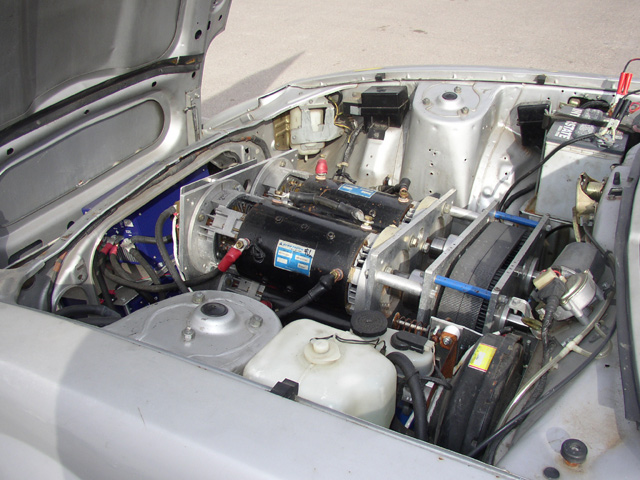
There's also the Silver Bullet, which has THREE motors.

<http://www.nedra.com/reports/pso04/pso04_photos&movies.html>

For a closeup of the motors:

<http://www.nedra.com/photos/pso04/silverbullet_motors_150.jpg>


On Nov 3, 2006, at 11:14 AM, David Dymaxion wrote:
<http://evcl.com/914/>

----- Original Message ----
From: Bruce <[EMAIL PROTECTED]>
To: [email protected]
Sent: Friday, November 3, 2006 9:38:19 AM
Subject: Re: Two Motor and Controller Setup
Has anyone actually built or seen such a setup with 2 motors driving
the
original transmission? How about posting a link to pictures of it?
--
Doug Weathers
Las Cruces, NM, USA
http://learn-something.blogsite.org/
--- End Message ---
--- Begin Message ---
Doug Weathers wrote:
For a closeup of the motors:

<http://www.nedra.com/photos/pso04/silverbullet_motors_150.jpg>
That would be the thumbnail - here is the full size picture:

http://www.nedra.com/photos/pso04/silverbullet_motors_640.jpg
--- End Message ---
--- Begin Message ---
Whoops, I linked to the thumbnail.  Here's the big people version:

<http://www.nedra.com/photos/pso04/silverbullet_motors_640.jpg>

On Nov 3, 2006, at 11:59 AM, Doug Weathers wrote:
For a closeup of the motors:

<http://www.nedra.com/photos/pso04/silverbullet_motors_150.jpg>
--
Doug Weathers
Las Cruces, NM, USA
http://learn-something.blogsite.org/
--- End Message ---
--- Begin Message ---
Tony Furr wrote:
I recently purchased a Vicor Megamod DC-DC converter (VI-26L-IU) from
surplus in hopes of using it with my 144v system. The sales spec
claimed "up to 300v", but the paperwork with the unit says the
low-line is 199v and a high-line of 399v (output voltage is 28v). A
call to Vicor support confirmed this won't work w/ my 144v system
since it will not power on below low-line.
Tony, the 26L has a nominal input voltage of 300VDC, and the input range
is 200 to 400VDC. The output is adjustable from 14V to 30.8V
A 25P would be ideal, but a 252, 251, 25N, or 253 would work.
FWIW, the part # breakdown is as follows. This is incomplete, but
covers common DC/DC voltages:
Part # format: VI-2XX-XX

First X is input voltage:
 Nominal    Range
0 12         10-20
1 24         21-31
W 24         18-36
2 36         21-56
3 48         42-60
N 48         36-76
4 72         55-100
T 110        66-160
5 150        100-200
6 300        200-400
7 150/300    100-375

Second X is output voltage:

Z 2
Y 3.3
0 5
X 5.2
W 5.5
V 5.8
T 6.5
R 7.5
M 10
1 12
P 13.8
2 15
N 18.5
3 24
L 28
J 36
K 40
4 48
H 52
F 72
D 85
B 95

Third X is temp range:

E -10 to 85C
C -25 to 85C
I -40 to 85C
M -55 to 85C

Last X is power (if vout >= 5V)

Y 50W
X 75W
W 100W
V 150W
U 200W
So it won't work for me, which is a shame because this is a nice
looking unit. It's new in the box and has never been installed. If
anyone is interested, contact me off-list. If you're looking for a
unit like this, you can get a great deal while helping me save the 15%
restocking fee they will charge me for the return.
tony furr
76 lancia scorpion EV
--- End Message ---
--- Begin Message ---
Lee Hart wrote:
That's great! So why don't you pick up the ball, and finish tracing
out Otmar's Curtis schematic, and add the PCB layout and mechanical
layout?
Eric Poulsen wrote:
1) I don't have a Curtis controller to trace.
That's easily fixed. Dead ones are fairly common. I learned to build
controllers by buying dead ones and doing an autopsy.
2) The Curtis design isn't all that great
No, it's not great. But it isn't bad, either. 90% of it is reasonably
well done. They used commonly available parts, and didn't sand off the
part numbers or pot it in epoxy. The parts that fail are known, so we
know what to fix in an improved design.
3) I'm not an EE, but I pretend to be one at home. Perhaps you know
someone who's more qualified?
Otmar is; and he's already donated a lot of time to the project. I and
others have done additional work, though it hasn't all been pulled
together into a nice neat schematic and parts list. Once that is done,
then someone needs to make a PCB layout.
I think you're missing the points I'm trying to make:
Perhaps you are missing mine, as well. I'm trying to say that if you
don't see what you want, then build it yourself (rather than whining
that someone else should do it for you for free).
1) Good schematics for building a high-power on-road EV motor
   controller don't exist for free...
Yes, they do! Otmar's Curtis, for example. It is a *good* schematic. Not
great, not perfect, but certainly good enough so anyone reasonably
skilled in the art can build one. Phillipe Borges posted a link to
another one earlier. I posted one for a Petrosonics controller. There
are dozens of others in manufacturer's application notes, engineering
textbooks, etc.
By nature, a schematic diagram is a summary of a design. It doesn't have
all the details, but it has enough so you can say, "Aha! I understand
how it works!" A block diagram is one step simpler; a wiring diagram is
one step more complex. There's at least a 10:1 difference in detail
between these steps.
If there were good schematics, PCB layouts, parts lists, etc available
for such a controller, I'd be willing to bet that someone (who lacks
the skills to design it) would at least attempt to build and use it.
Many people *have* built their own controllers, starting with exactly
the sort of schematics you are complaining about. That's what Otmar
Ebenhoech, Rich Rudman, Dale Glubrecht, Damon Crockett, Peter Senkowski,
and dozens of others have done. They learned a lot in the process. They
have been telling you it's hard work, it's expensive, and it didn't
really save money in the end. I'm sorry that you don't want to hear that
answer; but that's the way it turned out.
2) There are indeed people who are good at what they do, and release
their intellectual property to the public domain for the good of
others... Unfortunately, this sort of thinking doesn't seem to
   permeate much into the minds of those whose expertise is
   electronics hardware.
Hardware engineers have been doing this long before computers ever
existed. The literature is full of schematics, application notes, and
other free documentation for circuit designs. They are available in
books, magazines, and online, all free.
When you get the plans for building a house, they do not give you the
length for every piece of wood, or tell where to drive every nail. The
assumption is that anyone who sets out to build their own house will
have or learn the necessary carpentry skills to work out these details
on their own. If the plans included this detail, it would turn into a
huge book.
When you contribute a computer program, you do not include a complete
user's manual, or a tutorial of the C language you wrote the program in
so someone who doesn't know C will still be able to understand it. You
assume that the user is already skilled in using the computer, he knows
what the program is does, knows the language, and knows how to compile
it and install it on his system. If you tried to include this
information, it would take you 10 times longer to produce it.
Likewise, a schematic is just like the plans for a house, or the source
listing of a C program. They don't provide all the details so a complete
novice can build it. But, it *does* have enough data so anyone who knows
a little electronics (or is willing to experiment, or take a few
courses) can build it.
I think what you are asking for is the equivalent of the old Heathkits:
An electronic product designed and documented so thoroughly that anyone
could build it, with no prior electronics experience at all.
--
Ring the bells that still can ring
Forget the perfect offering
There is a crack in everything
That's how the light gets in    --    Leonard Cohen
--
Lee A. Hart, 814 8th Ave N, Sartell MN 56377, leeahart_at_earthlink.net
--- End Message ---
--- Begin Message ---
I'm looking for a dc/dc for the Yaris that is high amperage and was
wondering if anyone has used the IOTA product with a higher voltage
pack?
My pack will be 192-204V and the IOTA 55 or 75A AC/DC specs are as
follows:
108-132V model- can go to 180V DC as per Iota sales
220-240V model (55A MAX) - Not know yet by Iota as to how far outside
the range or if DC can be used
Has anyone used the 108 model with a high pack voltage or the 220
model with a 192 or lower pack voltage with any success?
Thanks,


Mark

http://www.iotaengineering.com/dls22055.htm

http://www.iotaengineering.com/dls75.htm
--- End Message ---
--- Begin Message ---
TEST sent 11/3/06 12:04 MT
Rush
Tucson AZ
www.ironandwood.org
--- End Message ---
--- Begin Message ---
On a related note, MicroChip has a new microcontroller lineup designed
for Motor Controllers:
PIC18F2331/2431/4331/4431

http://ww1.microchip.com/downloads/en/DeviceDoc/39616b.pdf
They even made a 800W BLDC/AC induction demo board around these chips,
with a combination hardware-based current limit interrupt + a software
controlled current limit mode:
http://ww1.microchip.com/downloads/en/DeviceDoc/DS-51453a.pdf
These *could* perhaps be used as a handy basis for a "universal" motor
controller - DC Series, BLDC, AC Induction - simply add the appropriate
daughter board and upload the correct firmware...
Just brainstorming here ;-)


14-bit Power Control PWM Module:
* Up to 4 channels with complementary outputs
* Edge- or center-aligned operation
* Flexible dead-band generator
* Hardware fault protection inputs (safety interlocks?)
* Simultaneous update of duty cycle and period -
Flexible special event trigger output

Motion Feedback Module:
* Three independent input capture channels -
Flexible operating modes for period and pulse width measurement
* Special Hall Sensor interface module
* Special event trigger output to other modules (simplifies programming)
* Quadrature Encoder Interface -
2 phase inputs and one index input from encoder
High and low position tracking with direction status and change of
direction interrupt
Velocity measurement

High-Speed, 200 Ksps 10-bit A/D Converter:
* Up to 9 channels
* Simultaneous two-channel sampling
* Sequential sampling: 1, 2 or 4 selected channels
* Auto-conversion capability
* 4-word FIFO with selectable interrupt frequency
* Selectable external conversion triggers
* Programmable acquisition time
--- End Message ---
--- Begin Message ---
Lee Hart wrote:
1) I don't have a Curtis controller to trace.
That's easily fixed. Dead ones are fairly common. I learned to build
controllers by buying dead ones and doing an autopsy.
If the price were right (low), I might just buy a dead one. Where would
you find such a thing?
2) The Curtis design isn't all that great
No, it's not great. But it isn't bad, either. 90% of it is reasonably
well done. They used commonly available parts, and didn't sand off the
part numbers or pot it in epoxy. The parts that fail are known, so we
know what to fix in an improved design.
When I look at that schematic, the control section seems really
old-fashioned. What's of particular interest is the power section and
the gate drivers, and the overcurrent sensing. Seems to me this is
where the focus needs to occur. Control is very important, but op amps
and complicated linear circuitry seems a bit much. Frankly, the control
portion is the part I consider the "easy" part, and the "deep magic"
involved in the power section is what I'm interested in.
3) I'm not an EE, but I pretend to be one at home. Perhaps you know
someone who's more qualified?
Otmar is; and he's already donated a lot of time to the project. I and
others have done additional work, though it hasn't all been pulled
together into a nice neat schematic and parts list. Once that is done,
then someone needs to make a PCB layout.
"The project" being the curtis reverse engineering? Most people don't
have good things to say about them.
I think you're missing the points I'm trying to make:
Perhaps you are missing mine, as well. I'm trying to say that if you
don't see what you want, then build it yourself (rather than whining
that someone else should do it for you for free).
Funny you should mention that. I have some surplus IGBTs and driver
circuits that I'm going to be toying with shortly. Expect questions
posted to the EVTech list soon.
1) Good schematics for building a high-power on-road EV motor
   controller don't exist for free...
Yes, they do! Otmar's Curtis, for example. It is a *good* schematic.
Not great, not perfect, but certainly good enough so anyone reasonably
skilled in the art can build one. Phillipe Borges posted a link to
another one earlier. I posted one for a Petrosonics controller. There
are dozens of others in manufacturer's application notes, engineering
textbooks, etc.
I'm not sure a schematic that says "Beware ... made from chicken
scratchings" is all you say it is. It's a good reference, maybe. But
my entire point was that is _isn't_ by any stretch of the imagination
something you could build a working controller from, especially when you
consider my comment above about the power section.
Mr. Borges schematic is (literally) unreadable, scanned at too low a
resolution. AFAIK, it's still like that. Has a better scan been uploaded?
If there were good schematics, PCB layouts, parts lists, etc
available for such a controller, I'd be willing to bet that someone
(who lacks
the skills to design it) would at least attempt to build and use it.
Many people *have* built their own controllers, starting with exactly
the sort of schematics you are complaining about. That's what Otmar
Ebenhoech, Rich Rudman, Dale Glubrecht, Damon Crockett, Peter
Senkowski, and dozens of others have done. They learned a lot in the
process. They have been telling you it's hard work, it's expensive,
and it didn't really save money in the end. I'm sorry that you don't
want to hear that answer; but that's the way it turned out.
Here's the part that I'm having trouble getting across: If I had two
choices of 1) Buying a $2500 controller and using it. or 2) Building a
controller for a whole lot more and releasing the design, I'd probably
choose option #2. The basis of this argument seems to be "you won't
save money."
I actually emailed Mr. Straubel, about his home-built controller, but no
response.
2) There are indeed people who are good at what they do, and release
their intellectual property to the public domain for the good of
others... Unfortunately, this sort of thinking doesn't seem to
   permeate much into the minds of those whose expertise is
   electronics hardware.
Hardware engineers have been doing this long before computers ever
existed. The literature is full of schematics, application notes, and
other free documentation for circuit designs. They are available in
books, magazines, and online, all free.
Mostly bits and pieces, but yes. I might like to point out that neither
books nor magazines are free, and don't tell me the library has this
sort of stuff, because they don't. I've checked.
When you get the plans for building a house, they do not give you the
length for every piece of wood, or tell where to drive every nail. The
assumption is that anyone who sets out to build their own house will
have or learn the necessary carpentry skills to work out these details
on their own. If the plans included this detail, it would turn into a
huge book.
The devil is in the details, especially with electronics. Houses aren't
a very good example.
When you contribute a computer program, you do not include a complete
user's manual, or a tutorial of the C language you wrote the program
in so someone who doesn't know C will still be able to understand it.
You assume that the user is already skilled in using the computer, he
knows what the program is does, knows the language, and knows how to
compile it and install it on his system. If you tried to include this
information, it would take you 10 times longer to produce it.
Not necessarily. I'm writing this email on a system that is built from
99% free software (Ubuntu Linux, Thunderbird Email, for those
interested. I do have some "non free" software installed). I could
download and modify any or all of the source, but I don't. It comes in
a nice clean package that's easy to install, even for grandma. What it
_isn't_ is a black box with a label on the outside that says "No user
serviceable parts inside."
If you're referring to my own project, then yes, you have to know how to
compile it, but my target audience knows this. Doesn't mean it can't be
packaged up in some pretty GUI for anyone to use, but it's unnecessary.
Likewise, a schematic is just like the plans for a house, or the
source listing of a C program. They don't provide all the details so a
complete novice can build it. But, it *does* have enough data so
anyone who knows a little electronics (or is willing to experiment, or
take a few courses) can build it.
Except that if you don't take care of overtemp, or induced noise, or
other nasties, it could catch fire.
I think what you are asking for is the equivalent of the old
Heathkits: An electronic product designed and documented so thoroughly
that anyone could build it, with no prior electronics experience at all.
Yes, except for the "no prior electronics experience" part.
--- End Message ---