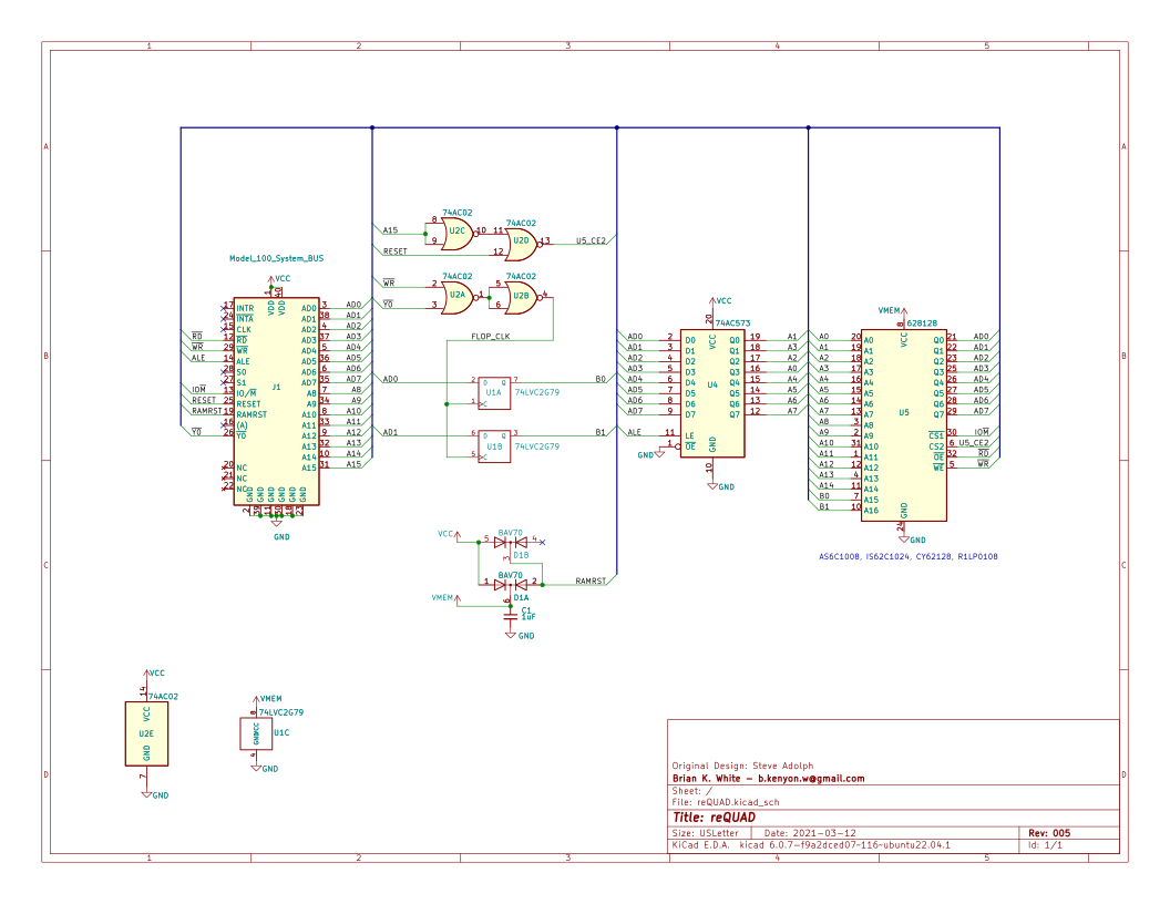
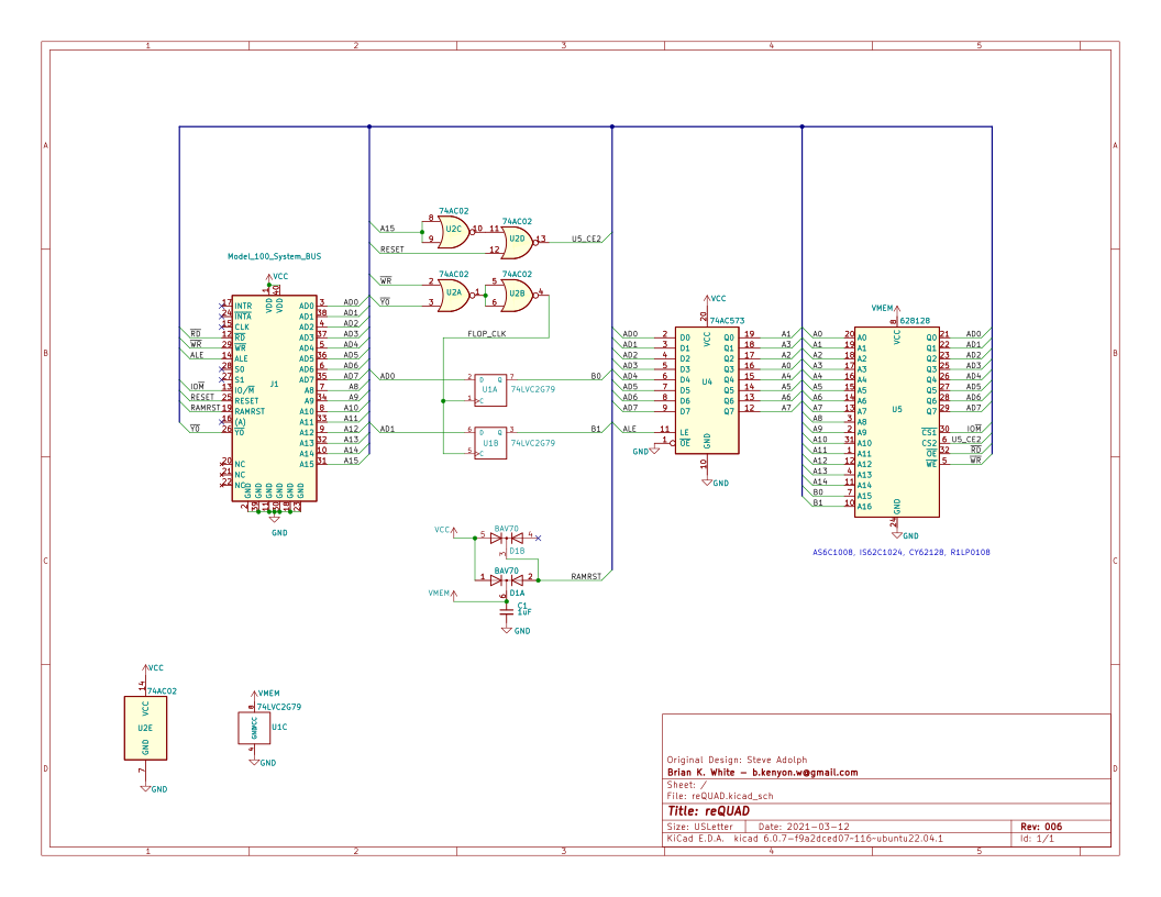
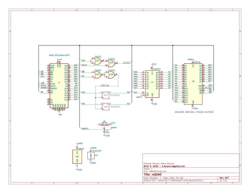
Updated. The main branch is now essentially v006 which adds back in a
diode I'd removed which backfeeds ramrst when vcc has power (to keep the
internal ram disabled), plus switched U2 to power from vmem, so now all
logic and ram are powered from vmem together, and same as before removes
the resistor-cap power-on-reset.
https://raw.githubusercontent.com/bkw777/reQUAD/main/PCB/reQUAD.svg
What was main below is now branch v008.
--
bkw

On 8/23/22 04:10, Brian K. White wrote:
Steve raised a couple questions about my changes to QUAD that I don't
have good answers for, so I added all my previous versions into that
github repo as branches named v001, v002 etc, because at least a few
of those DO work, especially the early versions before I got all hack
happy.
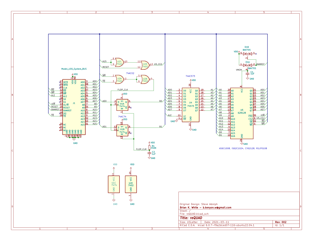
v002 is the version that exactly matches the QUADv2 schematic on
bitchin100
https://github.com/bkw777/reQUAD/tree/v002

I think I must have gotten my versions 1 & 2 files mixed up.

Looking at the different schematics, it looks like the progression goes:
v002 -initial - identical schematic to QUADv4 original (new pcb layout
though)
https://raw.githubusercontent.com/bkw777/reQUAD/v002/PCB/reQUAD.svg
For comparison:
http://bitchin100.com/wiki/images/7/7b/QUAD_schemactic.png
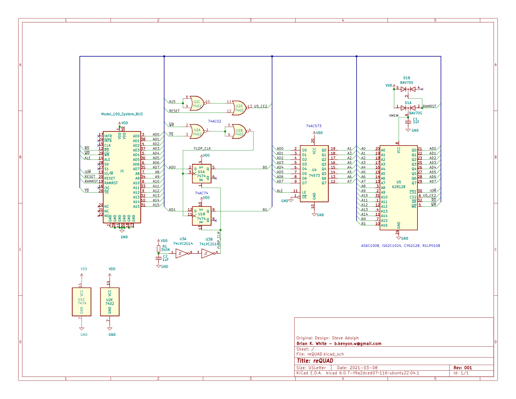
v001 - add schmidt triggers to power-on-reset output (I think this is
an idea Steve might have suggested to me to try)
https://raw.githubusercontent.com/bkw777/reQUAD/v001/PCB/reQUAD.svg
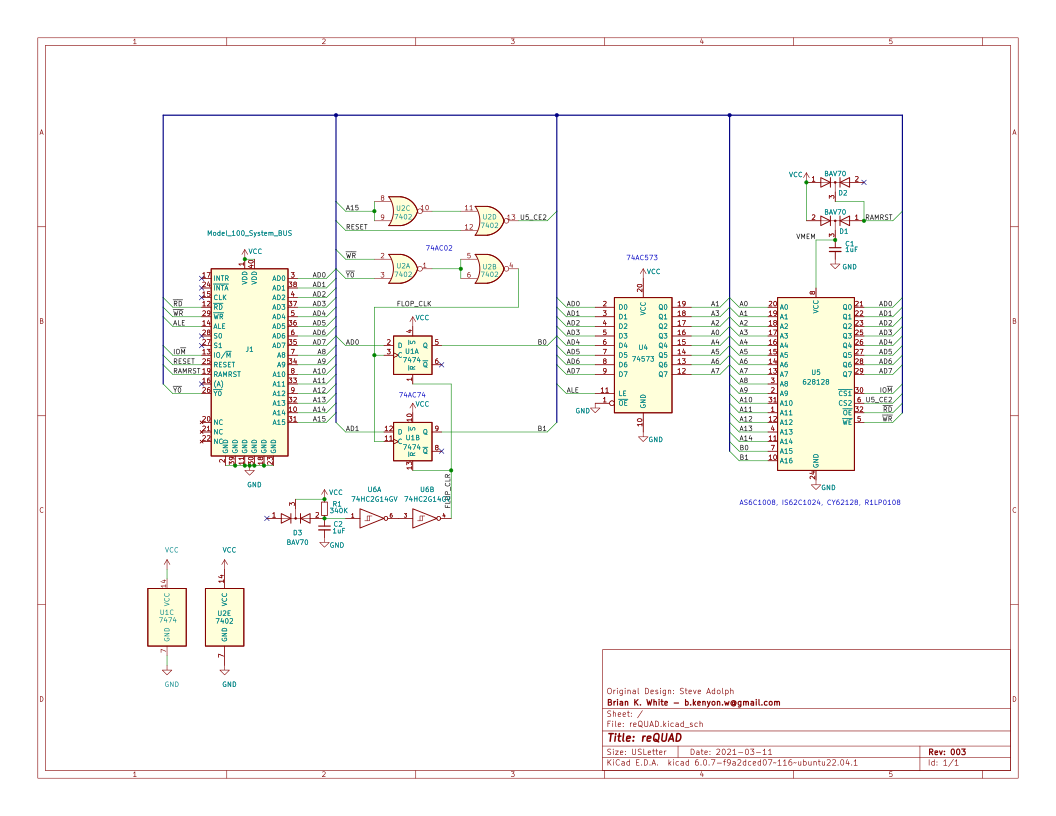
v003 - add a diode across the p-o-r resistor (I might have got this
from reading about r/c p-o-r circuits in general)
https://raw.githubusercontent.com/bkw777/reQUAD/v003/PCB/reQUAD.svg

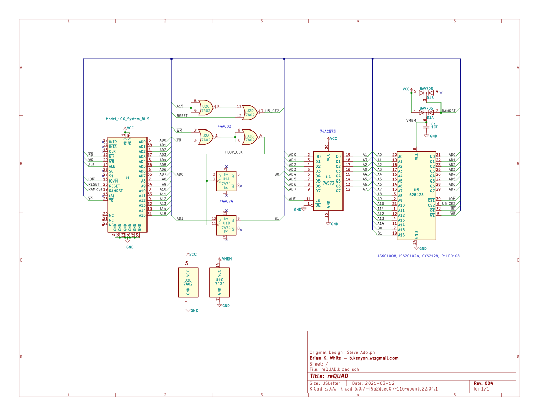
v004 - junk
https://raw.githubusercontent.com/bkw777/reQUAD/v004/PCB/reQUAD.svg
v005 - remove p-o-r, switch to a non-resettable flipflop, power
flipflop from vmem (fail to power u2 from vmem)
https://raw.githubusercontent.com/bkw777/reQUAD/v005/PCB/reQUAD.svg
v006 - same schematic as v005, pcb layout changes only (pull the chips
in from the ends so that a chip-puller doesn't hurt anything)
https://raw.githubusercontent.com/bkw777/reQUAD/v006/PCB/reQUAD.svg

v007 - junk (but one correct change: move U2 to vmem)
https://raw.githubusercontent.com/bkw777/reQUAD/v007/PCB/reQUAD.svg
main - junk - move ramrst, unshuffle the address lines output from U4
so that Q0 -> A0 Q1->A1 etc no idea if that was ok, I intended to test
https://raw.githubusercontent.com/bkw777/reQUAD/main/PCB/reQUAD.svg

So I think what we want is v006 but change U2 to get power from vmem.
Or one of v001,2,3 I'm not sure which is best, but any of 1-3 is
probably safe and more or less the same as the original.
At least a few of those versions do work, or at least appear to. I did
build a few and run them, but my testing was only cursory.
I think until further notice, consider this stuff food for discussion
only, not claimed to be good, especially the last version.
--
bkw