I applied 5v + ground to the proper pins. Pin 1 left
open.
Results vary from part to part, but within 10kHz of
1MHz.....especially if voltage is dropped to 4.1v.
3.3v output is further off.
I don't know if a load on the output makes a
difference...(load resistor value ? ).
Scope shows a square wave...but not a pretty one.
A 10nf cap across the power pins helps freq stability,
but does nothing to the scope image.
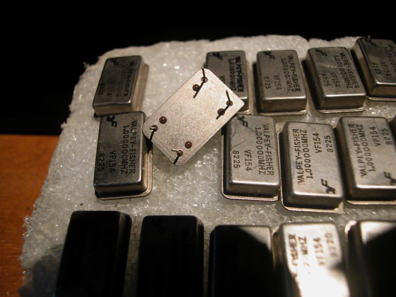
Is it pointless to attempt to get a good sine wave out
of this? ...or best to get a real sine wave part ?
These I'm guessing, are TTL/CMOS type.

=Randy=


==============

> Hi Randy:
>
> Those appear to be the very common 14 pin dip IC
> oscillators.
> pin 7 = ground
> pin 14 = Vdd
> pin 8 = Out
> pin 1 may be no connection or may be inhibit. Check
> with DMM in Ohm and diode
> function.
>
> It sure looks like:
>
http://www.valpeyfisher.com/images/productshots/xo/vf150.jpg
>
>
> Have Fun,
>
> Brooke Clarke
+++++++++++++++++++++++++
>
> Randy Leifer wrote:
> > Novice here.
> > I have a small electronics lab at home.
> >
> > PART 1:
> > I have these Valpey Fisher VF154 1 MHz
> oscillators.
> > I could not find any details at the VF website on
> this
> > particular model #. (OC, VC, ???)
> > Picture/link below....
> >
> > PART 2:
> > Does anyone have a link to a simple circuit, where
> I
> > could use these to get a stand-alone signal @
> around 1
> > or 2 volts?
> > This is just an educational value/exercise for me,
> I
> > don't really have an intended use (yet) for these.
> > I have some high-speed opamps and buffers....?
> >
> > Thanks,
> > =Randy Leifer=
>http://i5.photobucket.com/albums/y177/Midiot/DSCN3333.jpg
> >

=== message truncated ===


_______________________________________________
time-nuts mailing list -- [email protected]
To unsubscribe, go to https://www.febo.com/cgi-bin/mailman/listinfo/time-nuts
and follow the instructions there.