Bruce Griffiths wrote:
> Yet another option is to use the simple TAC (figure 2) in:
> http://n1.taur.dk/permanent/frequencymeasurement.pdf
>
> The only drawback with this circuit is that the capacitor voltage at
> reset isn't zero.
> The capacitor reset voltage is also temperature dependent.
> Since the change in the capacitor voltage is proportional to the
> synchroniser delay, the solution to this is obvious:
> Measure the capacitor reset voltage with the ADC and subtract it from
> the capacitor voltage held on the capacitor after charging is terminated
> by the STOP input.
> Dedicated ACMOS (or equivalent low output impedance) flipflops can be
> used to drive the diode switches directly.
>
The drawback turned out to be a useful feature.
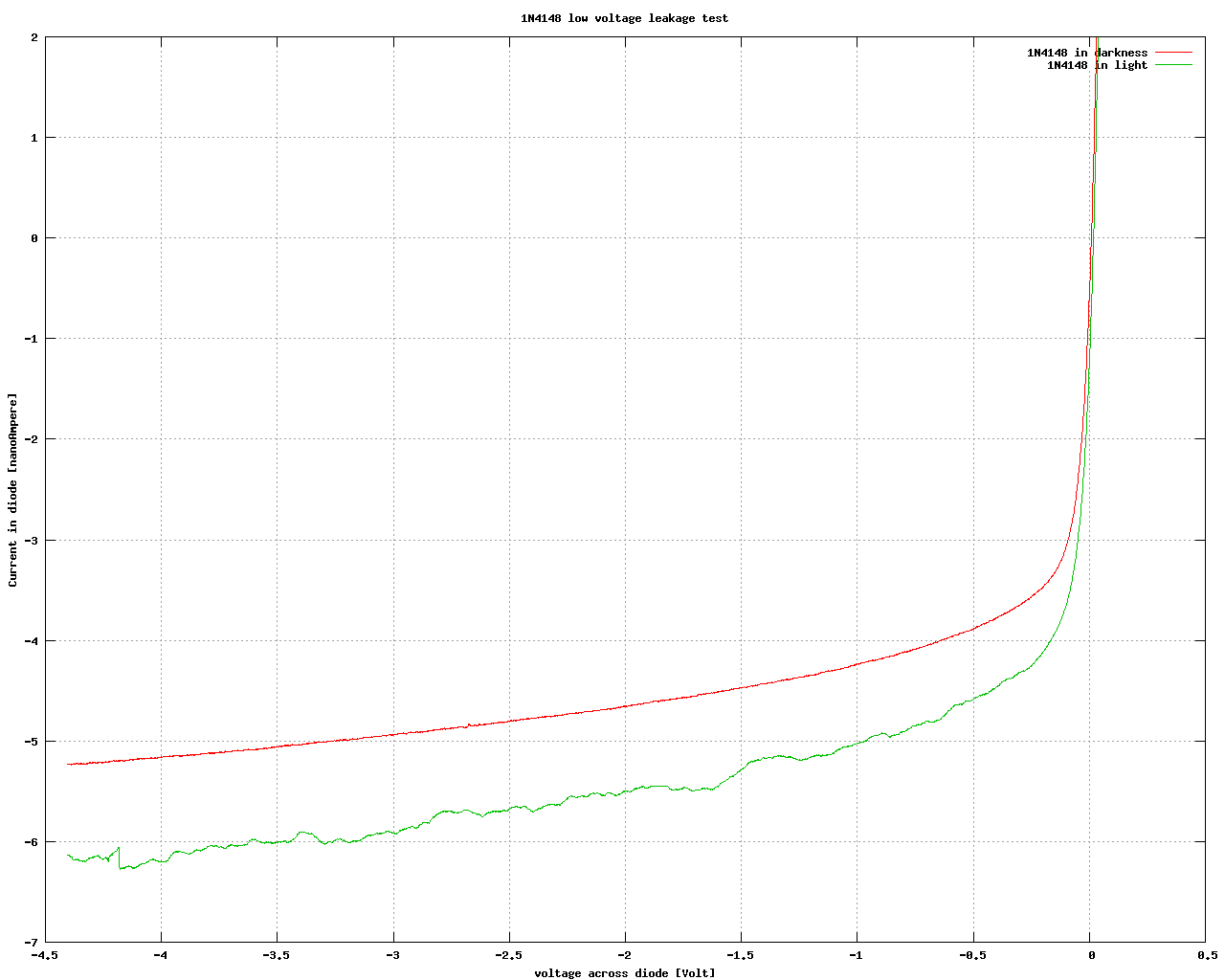
For one, the TLC072 opamp I used does not swing below V-+0.5V, and I had
no negative supply. Also, the 0.8V reset keeps me out of the worst
varactor-behaviour of the opamp's clamp diodes, and ditto the 'i' diode,
which would have caused some nonlinearity for short pulses. Finally, the
leakage of 'i' in hold has less variation over 0.8V-2.5V (1nA) than
0.0V-2.0V (5nA), http://n1.taur.dk/permanent/1n4148.png , which in turn
means that the delay from the stop to the adc s/h closes doesn't
introduce as much nonlinearity, as long as it is constant.

The way I do the subtraction is to measure the reset voltage after the
start-stop-convert-reset sequence (one could possibly misread your
description as suggesting converting the reset voltage first) and before
rearming - that way drift doesn't creep in while waiting for the edge.

The charge redistribution adc would have been good, true, but there
wasn't one in my junkbox.

/Kasper Pedersen

_______________________________________________
time-nuts mailing list -- [email protected]
To unsubscribe, go to https://www.febo.com/cgi-bin/mailman/listinfo/time-nuts
and follow the instructions there.