It is also used to check ROMs and RAMs for good data.

The service manual will often contain 'signatures' for each pinout of a device,
as it runs through a set, respective  routine.  Specific start, stop, and clock
signals are defined in the service manual.
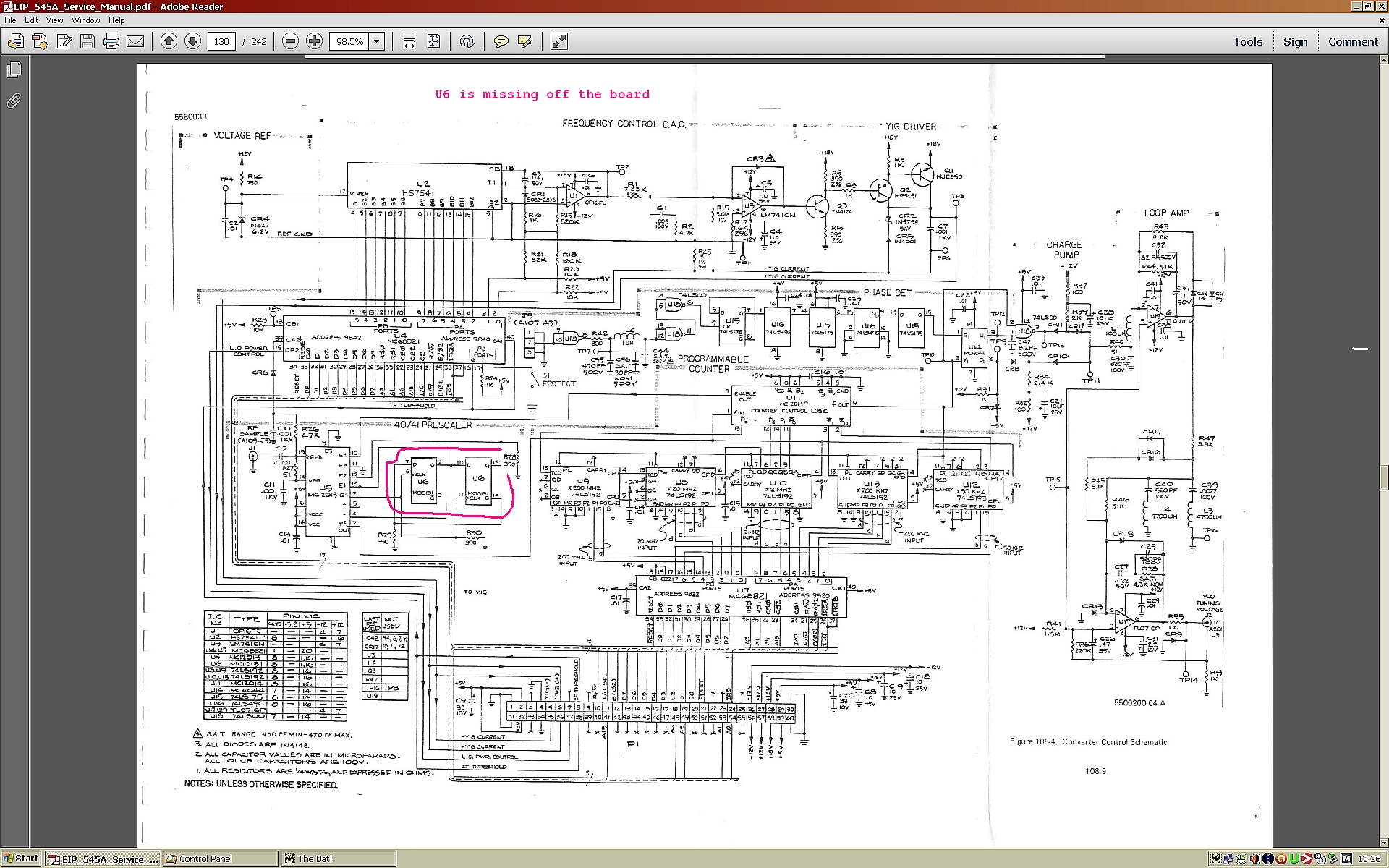
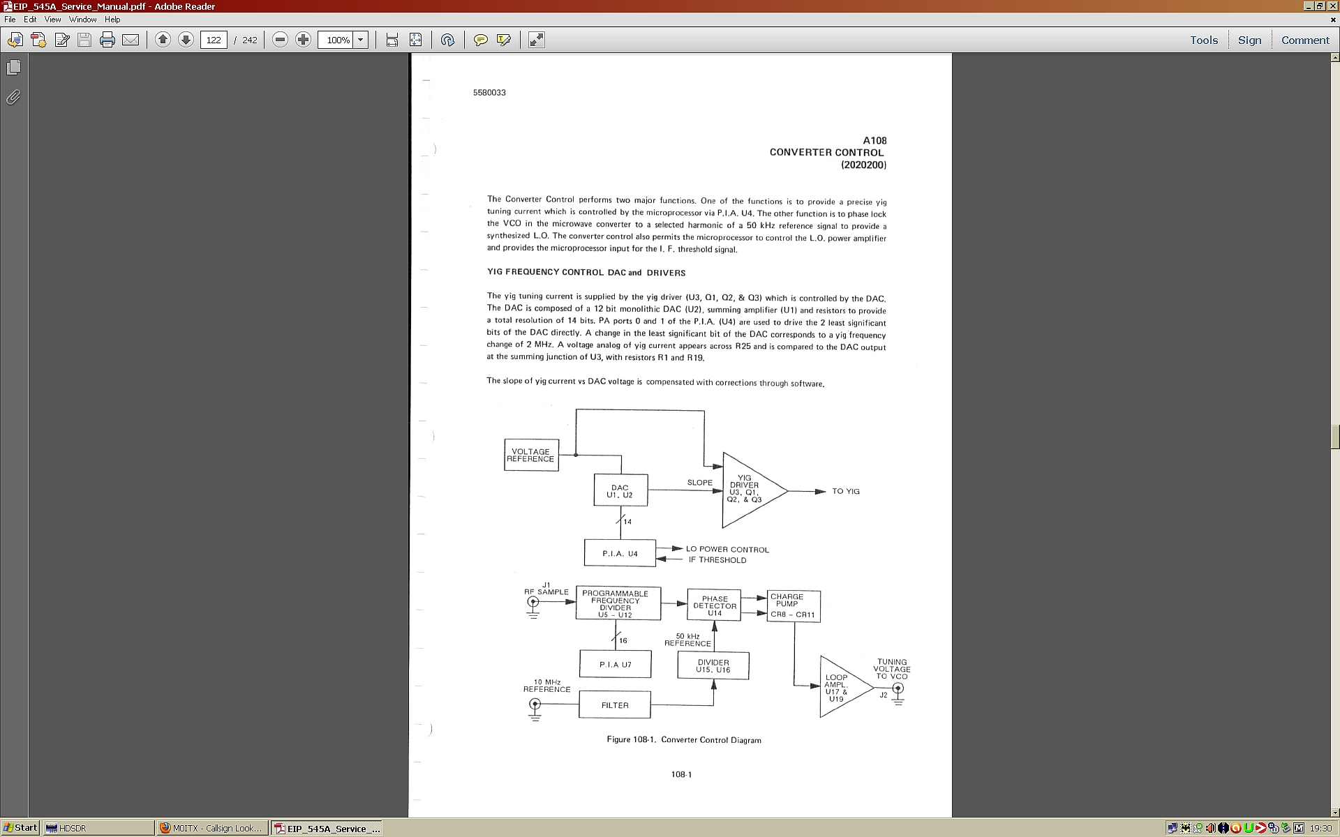
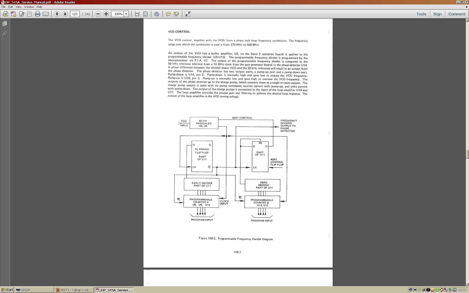
A very valuable tool. I have a 5005A.  Also comes equipped with a voltmeter,
ohmmeter and counter.  Nothing a nice logic analyzer can't do, ...just simpler
and quicker.

-Don


--------------------------------------------------
From: "Bob Quenelle" <[email protected]>
Sent: Tuesday, November 27, 2012 10:05 AM
To: "Discussion of precise time and frequency measurement" <[email protected]>
Subject: Re: [time-nuts] EIP545A 18GHz counter query

> Not that it's likely to help you, but a signature analyzer uses a shift
> register with feedback to generate a 4 hex character "signature" from a
> serial data stream.  It would only help if the troubleshooting tree includes
> a list a bad signatures for specific failures.
> http://www.prc68.com/I/HP5004.shtml
> Bob
>
> -----Original Message-----
> From: Chuck Harris
> Sent: Tuesday, November 27, 2012 7:45 AM
> To: Chris Wilson ; Discussion of precise time and frequency measurement
> Subject: Re: [time-nuts] EIP545A 18GHz counter query
>
> This one is usually an easy fix.  The EPROMS on the controller
> card are using tin plated sockets, and they become tin-whisker
> cities.  The counter will usually have enough oomph to blow any
> transient whiskers away if it is left running, but if it sits
> the whiskers will grow quickly and prevent the CPU from passing
> its power on self-test, and you get the "------" display.
>
> Take a high pressure air gun and blow under, around and through
> the EPROM sockets from all directions and angles.  When you plug
> the board back in, it should start to work again... for a while.
>
> A more permanent fix involves removing the sockets and replacing
> them with gold plated sockets with machined pins.
>
> Also, on many of the 545A counters there is a design mistake on
> the power supply board where the wire tie that holds an electrolytic
> capacitor passes through the board.  The holes the wire tie passes
> through are plated, and come through alongside of the +9V unregulated
> traces... bringing ground and +9V together.  Drill or file the plating
> out of the holes to prevent spurious blowing of the mains fuse.
>
> -Chuck Harris
>
> Chris Wilson wrote:
>>
>>
>>    27/11/2012 14:18
>>
>> I bought a 18GHz EIP545A counter which the vendor said was working
>> fine the day before and when on overnight soak test, and also when
>> last used some months ago. But when he checked it on the morning of
>> my coming over to see it he found it had developed a fault... I bought
>> it off him cheaply, as seen, hoping it might be fixable.
>>
>>
>> Here's the basic tale:
>>
>> It was acquired displaying just dashes. I checked the PSU voltages and
>> found the PSU section outputting well away from the manual figures. I
>> corrected these and checked supplies for ripple and they were all
>> good. I then decided to remove any board that was not essential to
>> operation. It came with a GPIB option board, so I pulled it. Luckily
>> this did some good and a working display appeared. There were three
>> tantalum caps on this board, as a matter of interest I pulled a leg on
>> each and tested them, all were OK. Refitting it killed the display
>> back to "dashes" again, so I set it aside as having an "unknown
>> fault", and continued. I can get it to accurately display up to
>> EXACTLY 188.9999 MHz Inputting 190.0000 MHz gives zeros. It has three
>> frequency bands. Band one works perfectly right up and well beyond its
>> 10 Hz to 100 MHz range. Band two often doesn't work at all, and just
>> displays zeros, it's a 50 ohm input, compared to the 1meg 20pF Band 1
>> input. Sometimes by ramping the frequency up slowly from 100 MHz I can get
>> a
>> seemingly random reading. Band 3, the GHz range, doesn't work at
>> all. Again, only zeros are displayed.
>>
>> The machine has quite a good range of self diagnosis tests. Tests are
>> via the key pad. The first test checks the VCO and other stuff, and
>> should display an accurate 200.0000 MHz It displays well over, always
>> in the range 253.5**** and the display isn't stable, it hovers over
>> several KHz. There's a tree menu to see where this issue could lie.
>> One limb suggests using a known good counter on the output of the VCO.
>> I did this and the output is miles high in frequency, about double,
>> and unstable. The tree menus goes on to suggest a phase lock circuitry
>> fault.
>>
>> Further tests seem to depend in part upon using something called a
>> Signature Analyzer, which I have never even heard of They suggest an
>> HP5004A, which is apparently pretty ancient. Is there a cheap way of
>> acquiring something to do this sort of testing? I believe given a few
>> pointers my scope, multi meter, sig gen and my other (working) Racal
>> counter could take me further.
>>
>> It's a nice old thing, and I would quite like a means of counting into
>> the higher frequencies it offers, but don't want to spend too much
>> time or money on it. It works a damned sight more than when it first
>> landed, which has kind of given me incentive to push a bit further,
>> given I have a .pdf copy of the repair manual. Here's the page of the
>> schematic I think is relevant, if it is a phase locked loop problem.
>>
>> This morning I realized there's a chip missing from a socket on the
>> board in question. It's U6, a flip flop, part of the pre scalar I
>> think? I assumed it was for some option, not fitted, but I am not so
>> sure now. A Chinese EBay seller is breaking one of these machines and
>> he lists all the boards separately, with decent photos. His board has
>> this socket populated, and looking at the schematic, (linked at the
>> bottom of this post), I think it's probably a vital component? I am
>> sure the seller must have known about this, but who knows...
>>
>> I have ordered a new chip and will fit it when it arrives tomorrow.
>>
>> Now, assuming I ever get this thing up and running fully, is there a
>> quick and dirty way of producing a test signal in the upper limits of
>> its range to check it out, given my Marconi sig gen stops at 1040 MHz?
>> Perhaps using a diode to give some harmonics?
>>
>> Diagram of the board I believe is faulty and missing the chip is at:
>>
>> http://www.gatesgarth.com/phaselockloop.jpg
>>
>> The text for this section, from the manual is at:
>>
>> http://www.gatesgarth.com/phaselocklooptext1.jpg
>>
>> and at
>>
>> http://www.gatesgarth.com/phaselocklooptext2.jpg
>>
>> Thanks for looking!
>>
>>
>
> _______________________________________________
> time-nuts mailing list -- [email protected]
> To unsubscribe, go to
> https://www.febo.com/cgi-bin/mailman/listinfo/time-nuts
> and follow the instructions there.
>
>
> _______________________________________________
> time-nuts mailing list -- [email protected]
> To unsubscribe, go to https://www.febo.com/cgi-bin/mailman/listinfo/time-nuts
> and follow the instructions there.
_______________________________________________
time-nuts mailing list -- [email protected]
To unsubscribe, go to https://www.febo.com/cgi-bin/mailman/listinfo/time-nuts
and follow the instructions there.