On 06/01/2018 12:04, Steve Malikoff via cctalk wrote:
Using the measurements provided by Vince I've rejigged the drawing a bit and it
ought to be closer.
Looks good to me except...
I had thought the hole in the front corner of the H960 was for a front panel
pivot, but it seems the foot
does actually use it.
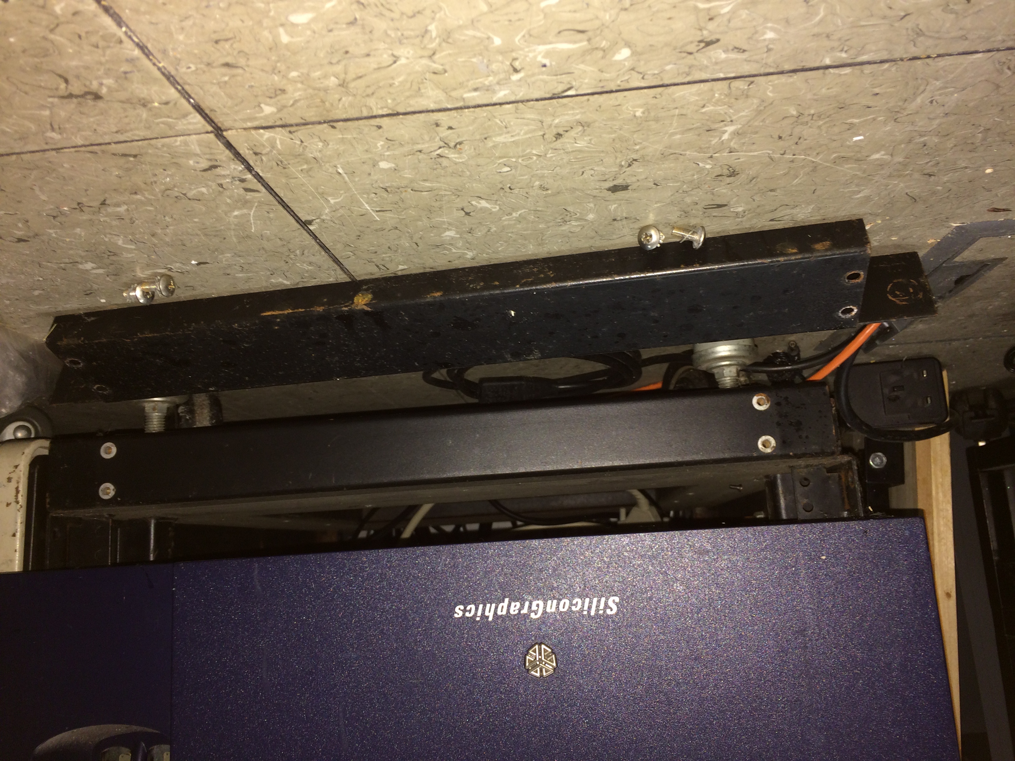
Yes, that's essential! But unlike in your drawing, the large screw that
holds the stabiliser foot into that hole is a large-head countersunk
screw, not a pan-head screw, and only the very bottom part of it is
threaded, 8-32 IIRC. The main part is a plain shank to fit the holes
for the front panel pivot and also the holes in the stabiliser; only the
part protruding below the stabiliser is threaded. It's fitted with a
shakeproof ("star") washer along with the nut, under the stabiliser. I
took all the stabilisers off my racks because they're superfluous in my
setup, and I can't remember where I put them, so I can't double-check.
I don't have the kickplate nor access to measuring one, so that probably
changes it a bit too.
That I do have, so I took it off one of the racks and you'll find some
(poor quality, from a phone that doesn't do close focus very well)
pictures at
http://www.dunnington.cx/DEC/H960/kickplate/IMG_0999.JPG
http://www.dunnington.cx/DEC/H960/kickplate/IMG_1000.JPG
http://www.dunnington.cx/DEC/H960/kickplate/IMG_1001.JPG
http://www.dunnington.cx/DEC/H960/kickplate/IMG_1002.JPG
http://www.dunnington.cx/DEC/H960/kickplate/IMG_1003.JPG

and a hastily drawn sketch of the dimensions at
http://www.dunnington.cx/DEC/H960/kickplate/kickplate.pdf
(NB This is a sketch, not a technical drawing, and is only approximately
to scale).
--
Pete
Pete Turnbull