On Sun, Nov 21, 2010 at 02:14:05PM -0800, Kirk Wallace wrote:
> On Sun, 2010-11-21 at 21:27 +0000, Leslie Newell wrote:
> > Yes it does sound like a variable reactor setup. The control signal is
> > DC and pushes the core into saturation, reducing it's inductance. The
> > early BOSS Bridgeport CNC mills used this sort of setup to reduce the
> > idle current on the stepper motors. It also used to be quite commonly
> > used on TIG welders to control the output current. These days they do it
> > with electronics instead.
> >
> > Les
>
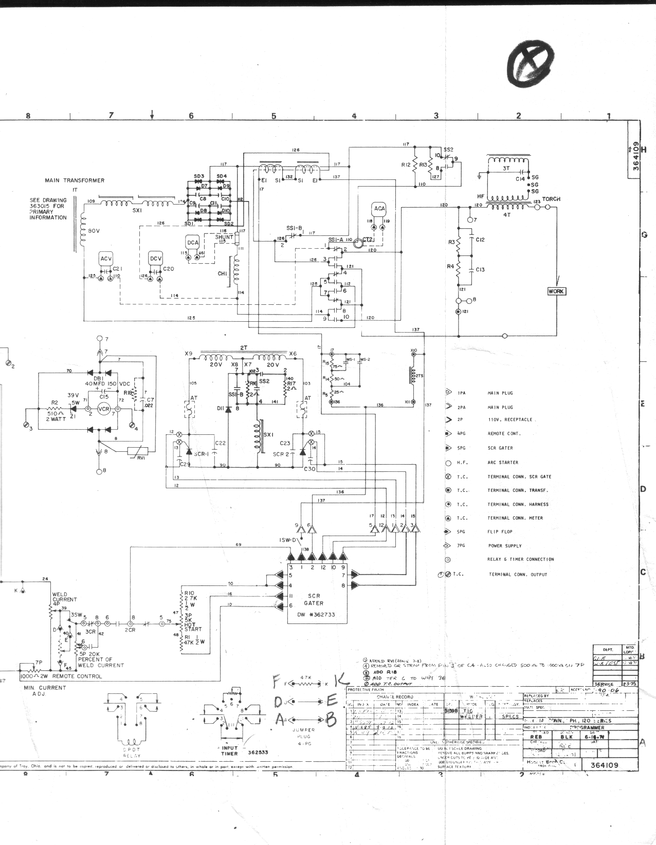
> See SX1 at E5 and G7
>
> http://www.wallacecompany.com/machine_shop/Hobart_Cyber-TIG/Manual/programmer/hobart_programmer-0051a.png
>
> (Short URL) http://alturl.com/2c8xe
Though I've only heard of them in whispers from prehistory, SX1 looks a
lot like a magnetic amplifier. The core of SX1 at both E5 and G7 show
that the material has a square B-H curve, as used for magnetic
amplifiers, and the presence and form of SX1 at G7, together with 2T at
F5, conform with "The typical magnetic amplifier consists of two
physically separate but similar transformer magnetic cores, each of
which has two windings ", read here:

    http://en.wikipedia.org/wiki/Magnetic_amplifier

In your case the DC seems to be generated by phase controlled
rectification of the induced AC in the control winding of SX1, with a
minimum DC level (bias) established by D11 and associated network.

> One of my problems is that I can't watch the meters while welding. It
> would be nice to have halscope as a voltage and current verses time
> display. This way I can see what happened after the weld is done, or
> maybe put a display in my helmet for a realtime display. While I am at
> it, I could replace the programmer (does current and gas cycle timing)
> with HAL too. But first, I need to get a good understanding of how the
> welder works.

I've started [2] a layout for a little AVR board (ATmega48) with 4
protected analogue inputs [3], and a midget ER400TRS 433 MHz
transceiver. Together with a second one with display, it's intended to
monitor haystack core temperature. (Moist hay results in spontaneous
combustion if temperature rises too high.) A pair like that, without all
the solar powered battery charging and management jiggery-pokery, could
monitor the welder, and provide a cordless data link up to 100m. (Even
if you use EMC at the welder end, something like the ER400TRS is easily
connected to a serial port, to link to a little board in the helmet.
Would more than textual values be needed as a real-time display?)

Erik

[2] Well, it's 3/4 done, but I keep improving it, and there's still the
    version without the solar guff, plus a few pins driving a two-line
    LCD, to do. I had planned that it would be close to the size of the
    LCD.

[3] I'll be running 4-20 mA current loops to them, but they handle
    simple voltage input, as is. With provision for an off-chip, but
    on-board, alternative voltage reference, I'll try to get a useful 9
    bits out of the 10 bit A/D, but 8 bits is all I'll bet on. Oh, yeah,
    the 4-20 mA line driver and transducer unit is still only a
    schematic.

--
"There is nothing new under the sun, but there are lots of old things
 we don't know yet."                                  -Ambrose Bierce

------------------------------------------------------------------------------
Beautiful is writing same markup. Internet Explorer 9 supports
standards for HTML5, CSS3, SVG 1.1,  ECMAScript5, and DOM L2 & L3.
Spend less time writing and  rewriting code and more time creating great
experiences on the web. Be a part of the beta today
http://p.sf.net/sfu/msIE9-sfdev2dev
_______________________________________________
Emc-users mailing list
[email protected]
https://lists.sourceforge.net/lists/listinfo/emc-users