> Thanks, John.  A few follow up questions...Is AC voltage harmful to the
> grid/anodes?  I have rectifiers handy and will convert it to DC, but was just
> curious about the implications of AC in this set up.  I have only really done
> DC stuff for the most part, so AC is a new chapter in my learning.
No, AC won't hurt them - like other triodes, a VFD will only conduct if the
anode is positive relative to the filament.

However, we usually use DC supplies for the grids and anodes because it's
simpler not to have to deal with transistors conducting in unexpected
directions and the like.

> I am also pretty unfamiliar with capacitive reactance but did some googling
> after your reply.  I will do some continued follow up, but if you have a
> second to look at this attachment, is the idea here the same concept as the
> section related to the capacitive transformerless PS?
> http://www.electro-tech-online.com/custompdfs/2004/09/00954A.pdf   I realize
> I am using a transformer, but I figured the step down concept was the same.

Yeah, it's essentially the same idea.  Luckily, for VFD filament supply, you
have a constant load and don't need regulator circuitry, just a fixed drop.

Let's assume we have a 24V transformer, and a VFD that has a filament that
takes 1.5 volts at 150mA.  What size capacitor would we need?  The first step
is to figure out what value to use if it was a resistance.  It would need to
drop 22.5 volts (24 - 1.5) at 150mA.  Ohm's law says R=E/I.  Note that I do all
my calculations in basic units (volts, amps, ohms, farads) and apply milli- and
kilo- and so forth later.  So 150mA is 0.15A.  Back to R=E/I, that's 22.5 volts
divided by 0.15 amperes, for 150 ohms.  Now to calculate a capacitor that would
have 150 ohms of reactance.  The formula for capacitive reactance is X = 1/(2
pi f C).  Rearranging to solve for C, I get C = 1 ( 2 pi f X).  As I live in
the United States, f is 60.  So I need 1 / (2 x 3.14 x 60 x 150) or 0.000 017 7
farads, which is 17.7 microfarads.

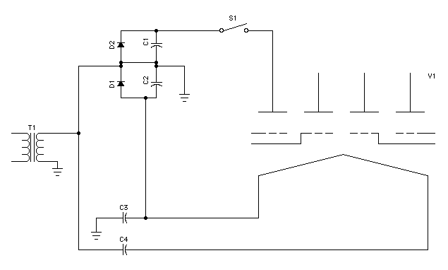
My original idea was to make a symmetrical circuit, with the filament
completely DC isolated from the transformer:

http://www.vitriol.com/images/tech/vfdps1.gif

I've deliberately ignored most of the details of the VFD drive, as this is just
a power supply illustration.

Note that in this case, two capacitors are used, effectively in series, so they
would each need to be half the reactance, which is twice the capacitance, or
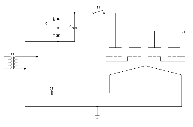
about 35 microfarads apiece.  Then I realized I didn't really need to isolate
the filament, I could just decide that one side of the transformer winding is
"ground", and reference my grid/anode supply to that:

http://www.vitriol.com/images/tech/vfdps2.gif

This uses one 18 microfarad capacitor instead of two 35 microfarad ones, which
is nice.  I used a different version of the voltage doubler for the anode/grid
supply too, but this seems like it ought to work.

Note that you'd probably want a third supply to power the logic, there are a
few different ways to address that (more if your transformer offers a center
tap).

- John

--
You received this message because you are subscribed to the Google Groups
"neonixie-l" group.
To post to this group, send an email to [email protected].
To unsubscribe from this group, send email to
[email protected].
For more options, visit this group at
http://groups.google.com/group/neonixie-l?hl=en-GB.