> I'm still experimenting with different techniques, but wanted to post an
> update.  I picked up a 6volt transformer just to play with.  I may not use it
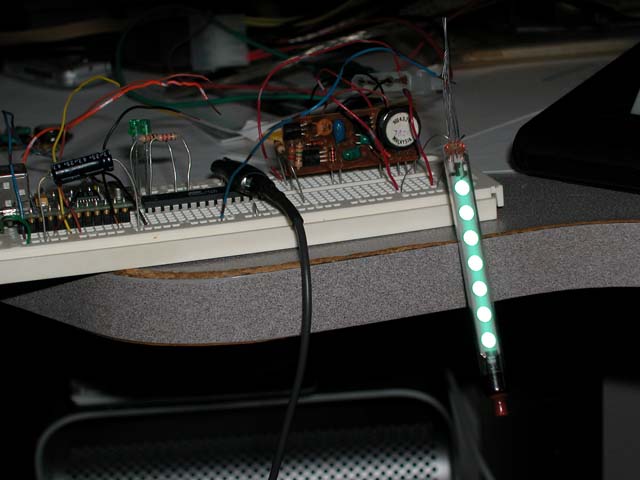
> in an actual clock circuit, but I hooked up 3 IV-11 filaments in series and
> dropped a diode into the start of the circuit.  I powered the grid/anodes off
> my 26VAC transformer.  It worked like a charm and I got all three VFDs lit!
Yup, that's some gratifying progress!

> The two transformer solution is not ideal in practice for a clock, but at
> least I'm able to get these babies lit easily on a breadboard.

It's a good way to learn the concepts.

>  I wish I had gotten into this hobby when LM9022s were still around!

There are several similar chips available.  Mike Moorrees has a similar lashup
too, using LM1877s:

https://skydrive.live.com/?cid=F9DB37B8211CE831&id=F9DB37B8211CE831%211410#cid=F9DB37B8211CE831&id=F9DB37B8211CE831%211914

https://skydrive.live.com/?cid=F9DB37B8211CE831&id=F9DB37B8211CE831%211410#cid=F9DB37B8211CE831&id=F9DB37B8211CE831%211915


> I'll continue to provide updates on my modest experiments for those
> interested.  I can't express how pleasing it is to simply get three of these
> tubes to light up on a breadboard!  Simple pleasures for simple minds.

We're all like that - there's nothing as fulfilling as having your own circuit
actually work:

http://www.vitriol.com/images/tech/vfd.jpeg

> I also have a question that is going to reflect my lack of knowledge with
> actual electronics circuits.  I had to connect the last of my filaments (what
> I will call ground) to one of the leads from the second transformer (25VAC
> secondary - the line on this transformer not going to the anodes/grid) to
> close the circuit and get things to light up.  If I wanted to keep the two
> power sources separate when I actually design my clock (i.e. 25V-60VDC to the
> grid/anodes) and 1.5VAC to each filament, how would I close the loop on the
> DC side?  Can I keep the power circuits separate with one for the filaments
> and one for the grid/anodes somehow or do I have to close the loop so that
> both of them are together.   Hopefully my question makes sense.

Yes, you do have close the loop.  The voltages on the grids and anodes are
referenced to the voltage on the filament, so the anode supply has to be
connected to the filament.

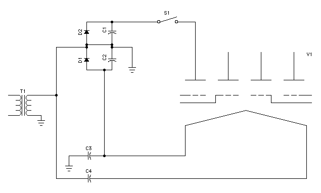
In the diagram where I isolated the filament, I had to add a connection to the
anode supply to get it to work:

http://www.vitriol.com/images/tech/vfdps1.gif

The connection is the one with the ground symbol hanging off of it.  When I
realized that is when I also realized that all the trouble I'd gone to, to
isolate the filament supply, was unnecessary!

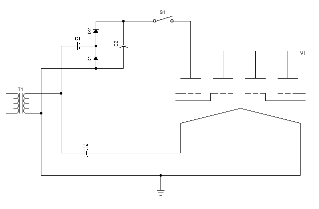
Then I went and rearranged things to take advantage of this realization to
simplify the circuit:

http://www.vitriol.com/images/tech/vfdps2.gif

So thank you for asking questions that caused me to learn something!

- John

--
You received this message because you are subscribed to the Google Groups
"neonixie-l" group.
To post to this group, send an email to [email protected].
To unsubscribe from this group, send email to
[email protected].
For more options, visit this group at
http://groups.google.com/group/neonixie-l?hl=en-GB.