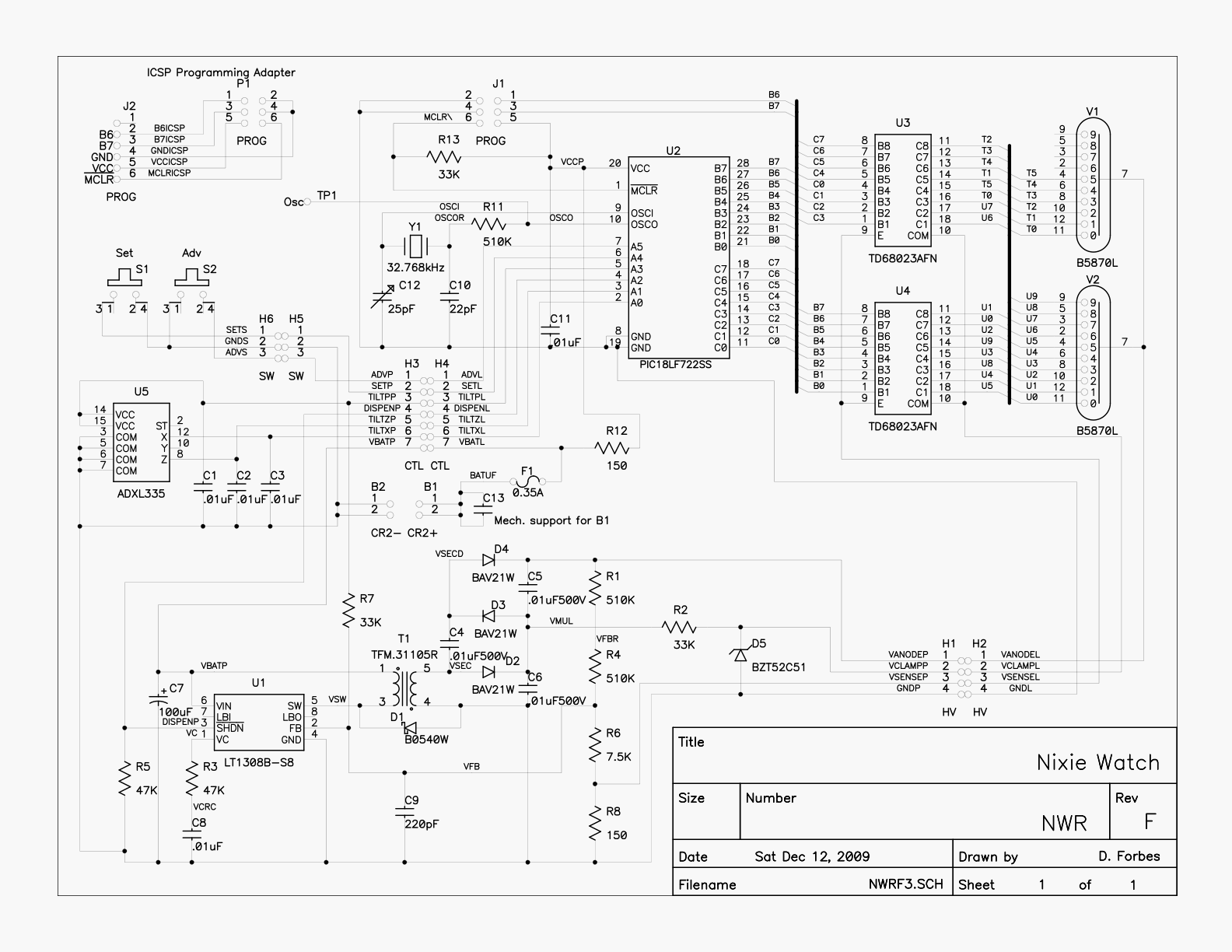
On Monday, 4 March 2019 04:12:55 UTC+8, nixiebunny wrote:
>
> The voltage applied to the elements of a Nixie tube is not as
> straightforward as you may think. Keep in mind that there is a voltage drop
> from anode to an 'on' cathode of ~130-140 volts, due to the ionized gas.
> Also, the capacitance of the tube elements and wiring has an effect on the
> switching behavior.
>
> I have successfully made several varieties of multiplexed Nixie clocks and
> watches using 60V or lower cathode switches. I used printed circuit boards
> to reduce capacitance, and adjusted the timing to allow the recently turned
> off cathodes to drift up to their natural 'off' voltage before turning on
> the next digit's anode.
>
> My Nixie watch design uses 50V cathode switch arrays. It also has no anode
> resistor. This is done by enabling only one cathode at a time, leaving the
> other tube with no cathodes enabled.
>
> The power supply has a resistor current sense and feedback mechanism to
> regulate the total current as well as the open-circuit voltage. Blanking is
> achieved by reducing the anode voltage to 100V, with a digitally controlled
> shift to the regulator feedback.
>
> So you can get good results with very little circuitry, if you apply a bit
> of cleverness to the problem.
>
> http://www.cathodecorner.com/nixiewatch/firmware/nwrf-schem.gif
>
> The feedback regulated power supply is a very elegant solution, and I'd
love to implement something like that, but my knowledge of switching power
supplies isn't good enough to pull it off.  I envy you.
--
You received this message because you are subscribed to the Google Groups
"neonixie-l" group.
To unsubscribe from this group and stop receiving emails from it, send an email
to [email protected].
To post to this group, send an email to [email protected].
To view this discussion on the web, visit
https://groups.google.com/d/msgid/neonixie-l/892ef4d6-d71e-45a8-ab96-30aa6beb5cc8%40googlegroups.com.
For more options, visit https://groups.google.com/d/optout.