After much cross checking between digits I have now settled on what I
believe the final measurements are and this is the result:
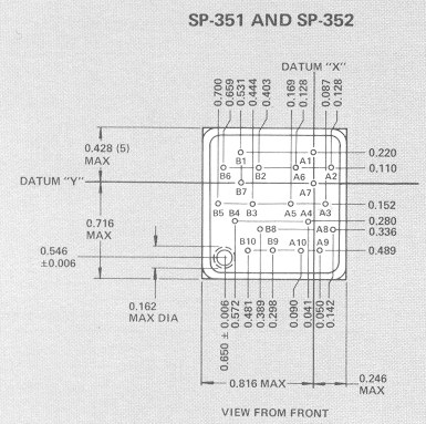
[image: crosscheck.JPG]

The left half will sit right on top of the right half so there is x & y
consistency between the two characters, the risk of the part fitting is
tending away from zero!

- Richard


On Monday, 6 November 2023 at 04:33:39 UTC Richard Scales wrote:

> Many thanks again,
> @Christian - that is a sound plan, will do/
>
> @Gregbert - noted though I never solder these things in, I make sockets
> for them every time which makes insertion/removal and replacement
> relatively easy. I purchase 40 way turned pin sockets and break the pin
> sockets out of them to fit into the right sized hole on the PCB and I
> always make an oversized hole for the 'glasshole'.
>
> I've already made footprints for many different displays including SP-33x,
> SP-35x,  SP-101 and  SP-151 - made as sockets.
>
>
> [image: QQPic.JPG]
>
> This is the display board for a different clock that uses SP-332 displays.
>
>  - Richard
>
>
> On Sunday, 5 November 2023 at 23:06:21 UTC gregebert wrote:
>
>> Make sure the holes for the display pins are larger than minimum; I made
>> my own footprint for the SP-151 and it was difficult to get the pins fully
>> aligned when trying to solder it in. Larger holes makes it much easier to
>> insert the display for soldering.
>>
>> Also beware of the *glasshole*, as I call it. It's the fill-tip when the
>> display gets gassed-up, and you need to make the PCB hole large enough to
>> accommodate slight manufacturing variances in diameter and location. I
>> think I used a 5mm hole, and keep traces spaced away as much as possible in
>> case you need to make the hole larger. I didn't have any glasshole
>> problems on my boards.
>>
>> On Sunday, November 5, 2023 at 9:35:11 AM UTC-8 Christian Riise Wagner
>> wrote:
>>
>>> Can't help you with better drawings, but I can recommend 3D-printing a
>>> small piece with the holes at the planned locations to verify the fit
>>> before sending off the board for production. I've used this technique
>>> myself a couple of times.
>>> søndag den 5. november 2023 kl. 16.12.59 UTC+1 skrev Dekatron42:
>>>
>>>> Have you asked Dieter if he has a better scan that he can share?
>>>>
>>>> /Martin
>>>>
>>>> On Sunday, 5 November 2023 at 05:30:53 UTC+1 Richard Scales wrote:
>>>>
>>>>> Thank you Benoit but I need actual data to make a footprint to use in
>>>>> PCB design application.
>>>>>
>>>>> I think I'm mostly there but was really seeking a better picture so I
>>>>> can confirm the accuracy of the supplied numbers and to which pins they
>>>>> apply - some of the ones buried in the centre of the display are not so
>>>>> clearly linked to the numbers at the side.
>>>>>  - Richard
>>>>>
>>>>>
>>>>> On Saturday, 4 November 2023 at 14:37:27 UTC Benoit Tourret wrote:
>>>>>
>>>>>> try to find 0.5 mm inner diameter pipe, 10cm long, fit all the pins,
>>>>>> pour some silicone, you should have a good representation of the
>>>>>> socket...
>>>>>> if you didn't forgot to add some wax or similar to unmold the silicon.
>>>>>> the more parallel your pipes will be, the more accurate your print
>>>>>> will be.
>>>>>> for a good print, the end of the pins is not important, the most
>>>>>> important is the place they have at the beginning, the nearest to the
>>>>>> display. without sacrifying a display; I don't see any other way to have
>>>>>> a
>>>>>> good measurement.
>>>>>>
>>>>>> Le samedi 4 novembre 2023 à 10:04:19 UTC+1, Richard Scales a écrit :
>>>>>>
>>>>>>> Hello, there are indeed a few the line up - it's the ones that don't
>>>>>>> that worry me the most!
>>>>>>>  - RIchard
>>>>>>>
>>>>>>>
>>>>>>> On Saturday, 4 November 2023 at 08:54:44 UTC Benoit Tourret wrote:
>>>>>>>
>>>>>>>> Hello Richard,
>>>>>>>>
>>>>>>>> have a look on the SP-351,
>>>>>>>>
>>>>>>>> https://www.tube-tester.com/sites/nixie/data/datasheets/SP-351_SP-352-drawing-01.jpg
>>>>>>>> [image: SP-351_SP-352-drawing-01.jpg]
>>>>>>>> not the same number of digit, but some of the pins should be
>>>>>>>> identical...
>>>>>>>> On my SP-356, there is 0 aligned pins on a diagonal way. only in
>>>>>>>> horizontal.
>>>>>>>>
>>>>>>>> Le samedi 4 novembre 2023 à 07:31:29 UTC+1, Richard Scales a écrit :
>>>>>>>>
>>>>>>>>> I used to so that but it relies on all the pins being straight and
>>>>>>>>> for this particular display - there are 30+ pins in a very small
>>>>>>>>> space -
>>>>>>>>> the more accurate the better - especially when it finally comes to
>>>>>>>>> plugging
>>>>>>>>> the things in!
>>>>>>>>> [image: TTPicture.JPG][image: PPpicture.JPG]
>>>>>>>>>
>>>>>>>>> Perhaps the differences are so subtle it's not worth worrying
>>>>>>>>> about. It's like staring at constellations! This group on the left
>>>>>>>>> seems a
>>>>>>>>> little out of alignment when compared with the image from Sperry,
>>>>>>>>> it's
>>>>>>>>> counterpart in the image for the character on the right looks more
>>>>>>>>> like my
>>>>>>>>> chart - yet - from the data I have logged - the chart shows similar
>>>>>>>>> groupings for left and right - is their image wrong ? is their data
>>>>>>>>> wrong?
>>>>>>>>>
>>>>>>>>> [image: DDpicture.JPG]
>>>>>>>>>
>>>>>>>>> When daylight comes I'll get eyes on the physical display though I
>>>>>>>>> fear at my age - that may be the least helpful method!
>>>>>>>>>
>>>>>>>>> - Richard
>>>>>>>>>
>>>>>>>>> On Saturday, 4 November 2023 at 06:09:25 UTC Audrey wrote:
>>>>>>>>>
>>>>>>>>>> You could scan the bottom of one using a scanner and convert to
>>>>>>>>>> inches/mm using the DPI.
>>>>>>>>>>
>>>>>>>>>> On Sat, Nov 4, 2023, 2:04 AM Richard Scales <
>>>>>>>>>> [email protected]> wrote:
>>>>>>>>>>
>>>>>>>>>>> I'm looking for any details of the pinout of the Sperry /
>>>>>>>>>>> Beckman SP-252 Multi Segment display which are any better than the
>>>>>>>>>>> one that
>>>>>>>>>>> I found over at tube-tester.com:
>>>>>>>>>>> https://tube-tester.com/sites/nixie/data/SP-252/sp-252.htm
>>>>>>>>>>>
>>>>>>>>>>> I'm making a footprint and need to get the pin positions as
>>>>>>>>>>> accurate as possible. My usual process for this is to copy the pin
>>>>>>>>>>> positions into a spreadsheet and make a scattergram which should
>>>>>>>>>>> represent
>>>>>>>>>>> the pin positions.
>>>>>>>>>>>
>>>>>>>>>>> This allows me to spot any obvious blunders. It's just that the
>>>>>>>>>>> image I have is not that clear and there is some information
>>>>>>>>>>> missing (IMHO)
>>>>>>>>>>> so if anyone can point me to anything better I would be most
>>>>>>>>>>> grateful.
>>>>>>>>>>>
>>>>>>>>>>> I could not find it in the Sperry Information Systems catalogue
>>>>>>>>>>> for which I already have a PDF.
>>>>>>>>>>> - Richard
>>>>>>>>>>>
>>>>>>>>>>> --
>>>>>>>>>>> You received this message because you are subscribed to the
>>>>>>>>>>> Google Groups "neonixie-l" group.
>>>>>>>>>>> To unsubscribe from this group and stop receiving emails from
>>>>>>>>>>> it, send an email to [email protected].
>>>>>>>>>>> To view this discussion on the web, visit
>>>>>>>>>>> https://groups.google.com/d/msgid/neonixie-l/171bf56b-7195-454e-8ebb-2ef9aceb2e78n%40googlegroups.com
>>>>>>>>>>>
>>>>>>>>>>> <https://groups.google.com/d/msgid/neonixie-l/171bf56b-7195-454e-8ebb-2ef9aceb2e78n%40googlegroups.com?utm_medium=email&utm_source=footer>
>>>>>>>>>>> .
>>>>>>>>>>>
>>>>>>>>>>

--
You received this message because you are subscribed to the Google Groups
"neonixie-l" group.
To unsubscribe from this group and stop receiving emails from it, send an email
to [email protected].
To view this discussion on the web, visit
https://groups.google.com/d/msgid/neonixie-l/b00a8edb-1595-4945-ac8a-7bd6592a9f9an%40googlegroups.com.