JR
I have build also QSD based on the QEX article.
In the QSD the phase difference is 90 degree.
But i am interested in your design.
73 Johan PA3GSB
--- In [email protected], "jr_dakota" <[EMAIL PROTECTED]> wrote:
>
> If you copied the DDS output circuit from the QEX article it will
NOT
> work and was obviously untested at the time of printing .... The
first
> error is trying to bias the LVDS output amps like they are the
> internal comparator in the 9854 ... An LVDS amp is a differential
amp
> like a balance microphone amp (The article also uses one after the
> mixer for an example of a diff amp) and wants to see a differential
> (180 degrees out of phase) signal with NO BIASING .... the LVDS
amps
> are interally biased to act similar to a comparator as was as
acting
> like a differential amp and it's purpose is to receive a digital
> signal from a cable, amplifiy it and clean up the losses due to
cable
> capacitance which 'squares up' the output ... the LVDS was a good
> choice and Gerald kept it after correcting the errors, I measured
> about a 5-6DB increase in spur reduction over the stock outputs of
the
> IQ-VFO kit ... part of this is due to using 200 ohm filters which
> lowers the necessary current and partly due to the LVDS amps
>
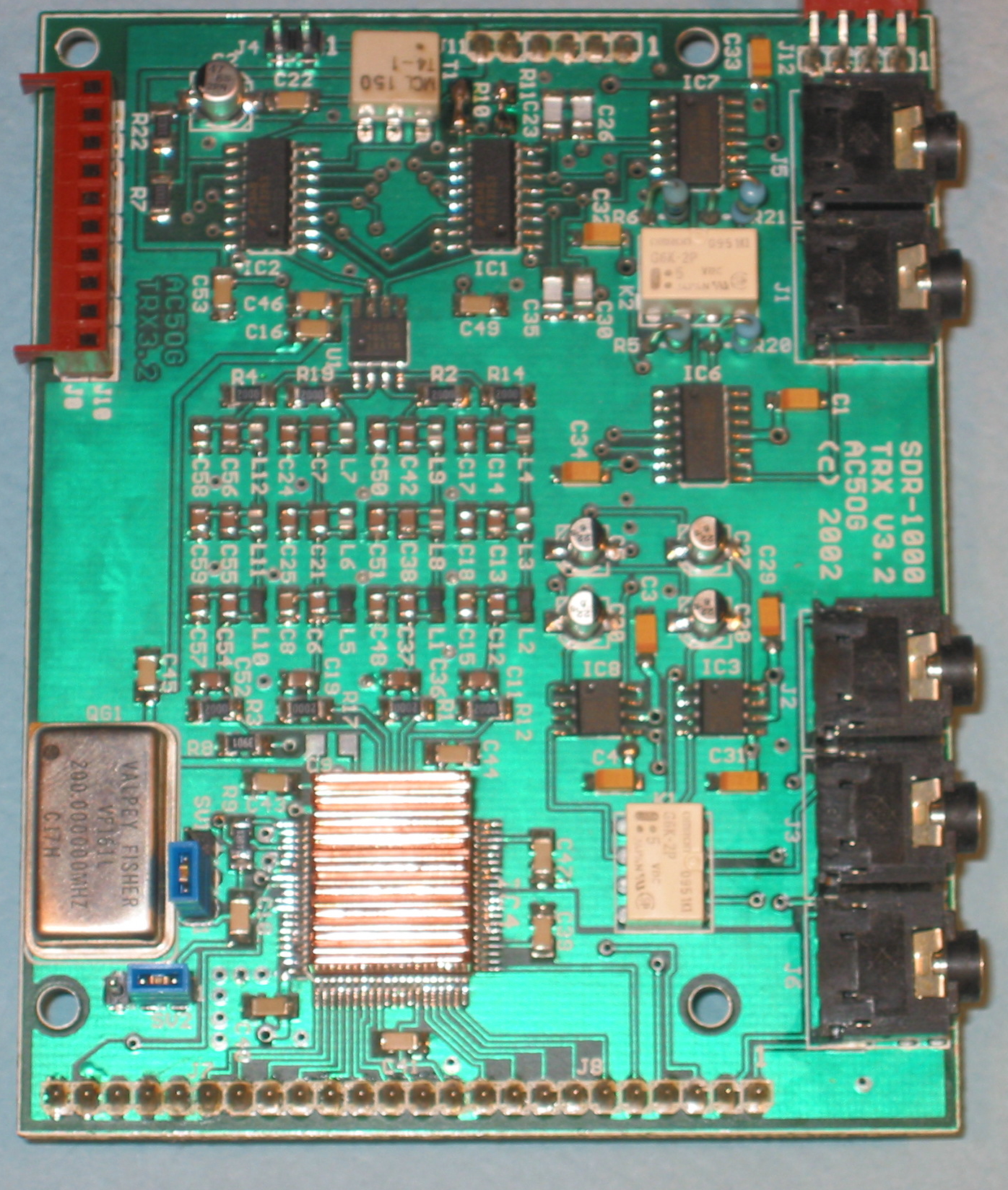
> The second mistake is you need a low pass filter on each
differential
> output, 4 total in the case of the 9854 .... here's a picture of
the
> final design of the SDR-1000 and on the left, just above the
> heatsinked 9850 you can clearly see the 4 filters
> http://www.tracey.org/wjt/sdr1k/sdr-board-pics/trx-top.jpg
>
> If these things aren't corrected you will not get a 90 degree
> quadrature output, or anything even close enough to be software
> corrected, which sounds exactly your situation now
>
> I have a schematic of a working design using a MAX9172 which is
> Maxim's version of the chip Gerald uses and is 100% compatable ...
My
> low pass filter is different than others (After numerous
simulations
> I'm convinced an elliptic filter is a poor choice for low Q surface
> mount inductors and a Chevyshev low pass is better using surface
mount
> inductors. If you use higher Q [and much larger} inductors then the
> Elliptic makes sense) but you can just substitute 2 more of the low
> pass filters you already have and you can see how to correctly feed
> them to the output amps
>
> If you are indeed using the LVDS amps like in the QEX article and
> it's OK with Alberto I can upload the schematic and a picture of my
> circuit laid out on a section of SMT protoboard
>
> JR
>
> --- In [email protected], "jeanrenier2004"
> <jean.taeymans@> wrote:
> >
> > Hi everyone,
> >
> > I am new to this discussion group, so I may comment about items
that
> > have been covered before, please bear with me.
> >
> > I am currently finishing an home build SDR receiver front end
> > project (very much) based on Gerald Youngblood's design
published
> > back in 2003. It is based on an AD9854 IQ local oscillator and a
QSD
> > plus a pair of amplifiers, the whole being preceded by a set of
HF
> > filters.
> > I have written a little application in VB6 in order to control
the
> > DDS frequency and the HF filter bank using the parallel port.
> > Nothing fancy, just to run some tests.
> > Currently I use the following set-up: the audio output of the
SDR is
> > connected to an SB Audigy SE sound card of my desktop PC (the
laptop
> > has no stereo audio inputs) which is running SDRadio (version
0.99),
> > while the control part is connected to the parallel port of my
> > laptop PC (the desktop having no free parallel port). It is bit
> > awkward, but it OK for testing, I'll buy a LPT/PCI card for the
> > desktop one of these days.
> >
> > SDradio works great, it is a really remarkable piece of
programming,
> > good demodulation in AM and SSB (I did not try NBFM yet). The
low
> > frequency noise, some 3kHz both sides of the 0Hz is very well
> > visible (and audible), but can be avoided altogether by tuning
> > SDRadio some 5...10kHz up or down.
> >
> > I have a problem though, for some reason I can not fully
calibrate
> > the skew of the SB Audigy board, both the phase and amplitude
> > cursors should actually be set to some position outside their
range.
> > I did the same exercise with an old SB PCI128 board, this one
can be
> > calibrated all right within the range of the cursors.
> > I prefer however to use the SB Audigy board, as it has the full
96dB
> > dynamic range when used at 16 bit resolution, which is some 10dB
> > more than the SB PCI128 board.
> >
> > Another thing that would be nice, is the possibility to set the
> > centre frequency of the spectrum display of SDRadio by an
external
> > program, the little application in VB6 in my case. So that it
would
> > be possible to actually change the frequency including the
spectrum
> > display in one single GUI action. Maybe having some API on
SDRadio
> > or possbly a global variable that would be read by SDRadio.
> >
> > As I use to listen in on the digtal modes (RTTY, HF fax, ...) I
use
> > other programs such as Hamscope connected to the output of
SDRadio.
> > This is done by actually patching the analog signal from the
line
> > out of one sound board (the one with SDRadio) to the line in of
the
> > other sound board (the one with Hamscope). It would be nice if
> > SDRadio would have some means to perform this on the internal
> > digital signal, avoiding a DA and AD conversion.
> >
> > Thanks for any help or advise and all the best,
> > Jean.
> >
>
SPONSORED LINKS
| Ham radio | Craft hobby | Hobby and craft supply |
YAHOO! GROUPS LINKS
- Visit your group "soft_radio" on the web.
- To unsubscribe from this group, send an email to:
[EMAIL PROTECTED]
- Your use of Yahoo! Groups is subject to the Yahoo! Terms of Service.