(squares up) the signal after passing through a cable (not a coax
usually but a differential shielded pair like a balanced mike cord)
but it is also a differential amp and like all differential amps it
rejects noise in the common mode, the main reason for using
differential (balanced) cable .... it's intended purpose is mainly for
DSL signal processing after it comes from a long noisy cable run ...
although in our case we don't really use or need the common mode
rejection, it is handy for gaining 6db with the same current in the
9854 (Or lowering the current for the same voltage output which cleans
up the spurs a bit) ... I don't remeber if I mentioned it here or in
personal correspondance off list but by using the LDVS amp and 200 ohm
filters (and lowering the output current) I was able to gain 5-6DB
spur reduction as compared to the original I-Q VFO output design of
AA0ZZ which I consider quite significant
The best way to look at it is probably as a Differential Comparator
... still you can NOT externally bias one like the QEX article or you
ruin the internal biasing, speed, and output duty cycle
The reason you must use a filter on each half of the differential
input is otherwise you'll lose your 180 degrees difference as one side
will be phase shifted by the filter and the other side won't ... You
don't lose the 90 I-Q phasing but instead lose your 50% duty cycle
which has a similar effect with a QSD detector
JR
--- In [email protected], "jeanrenier2004"
<[EMAIL PROTECTED]> wrote:
>
> J.R., many thanks for your comments, I only wish I got them
> earlier. First of all, my design (or rather Gerald Youngblood's)
> works otherwise OK, it receives HF signals where it should, etc. Its
> MSD is well below 1µV and its noise and intermodulation
> characteristics seems to be great. I didn't run all the tests yet,
> especially (I must confess) not those above 15MHz (lack of an
> adequate signal generator and some other issue, see further).
>
> Having reflected about the asymmetric inputs of the LVDS receiver
> for the better part of the weekend, I still believe it should not be
> the source of important I to Q phase errors.
> The DACs inside the AD9854 generate a current proportional to the
> signal on e.g. IOUT1 while they will generate the complementary
> signal on IOUT1B. IOUT1 is terminated by a 180ohm resistor (in my
> design) in parallel with the input impedance of the LPF (also
> 180ohm), while IOUT1B is terminated by a 100ohm resistor (it should
> be 90ohm). The output of the LPF is terminated on its turn with
> 180ohm and led to the negative input of the LVDS receiver. This
> signal should be a beautiful sine, and to the best of the abilities
> of my old oscilloscope it is.
> IOUT1 and IOUT1B are furthermore each sampled with a 10kohm
> resistor, decoupled with a 10nF capacitor and led to the positive
> input of the LVDS receiver. This forms a 1st order LPF at ca. 1.5
> kHz (several orders of magnitude lower than the signals of
> interest). The signal on this line is essentially nothing more than
> a DC voltage of the average of the IOUT1 and IOUT1B.
> I use a MAX9113 for the LVDS receiver; to my perception it is
> nothing more than a voltage comparator (albeit fast). It just
> squares faithfully the sine coming from the LPF and will not care if
> one of its inputs is just DC.
> All possible phase / amplitude errors would be present on the I path
> as well as on the Q path. As we are only interested in the correct
> 90° phase relation between both paths, so most of the errors should
> cancel.
>
> Now, since the Flex-Radio design appears to use a symmetric input to
> the LVDS receiver, there must be a reason for it (by the way, was
> the final design ever published ?). I would suspect it may cancel
> other asymmetries and phase errors nearer the corner frequency, I
> will have to do more thinking about that.
> The LPF is not the original QEX design, as I had only 1µH SMD selfs
> handy, I changed the design a bit, it is still a 7th order elliptic,
> but its impedance is 180ohm, and the corner frequency is ca. 33MHz.
> It is build with 3 times 1µH selfs in the series path and 4 times
> 39pF in the parallel path, the selfs are bridged with 8.2pH, 3.9pF
> and 1.2pF.
> I have still some more of these 1µH selfs, so I can have a symmetric
> input on the LVDS receiver (there is still some space in the box).
> I am much interested in your comment about an elliptic filter being
> not optimal when using low Q selfs, and I would be grateful if you
> would share your design with the rest of us.
>
> I got into another issue with the QSD design I didn't think of
> before. When clocking the FST3253 chip at high frequencies there is
> inevitably some local oscillator signal leaking towards the
> antenna. This is due to the gate channel capacitances of the actual
> switch transistors inside the FST3253. These capacitances are
> probably no more than a few pF (I could not find a figure in the
> data sheet) but each pF represents already an impedance of ca 7kohm
> at 22MHz. This leak signal is phase shifted by the output impedance
> of the antenna / filter system and is subsequently demodulated as DC
> by the QSD itself.
> I observed frequency dependent DC values of several tens of mV
> differential over the two pairs of storage capacitors, higher with
> the higher frequencies and kind of "spread" over the I and Q
> outputs.
> These DC signals would not bother anything, if they would not
> saturate the amplifiers (which are fed at -6V and +6V). This is
> alas the case at the maximum gain (40dB) and at frequencies above
> 22MHz.
> Can somebody advise about how to avoid this phenomenon? Is a set of
> DC block capacitors (e.g. 10nF) just at the input of the amplifiers
> a good idea?
>
> Many thanks and all the best,
> Jean.
>
>
> --- In [email protected], "jr_dakota" <SG2112@> wrote:
> >
> > If you copied the DDS output circuit from the QEX article it will
> NOT
> > work and was obviously untested at the time of printing .... The
> first
> > error is trying to bias the LVDS output amps like they are the
> > internal comparator in the 9854 ... An LVDS amp is a differential
> amp
> > like a balance microphone amp (The article also uses one after the
> > mixer for an example of a diff amp) and wants to see a differential
> > (180 degrees out of phase) signal with NO BIASING .... the LVDS
> amps
> > are interally biased to act similar to a comparator as was as
> acting
> > like a differential amp and it's purpose is to receive a digital
> > signal from a cable, amplifiy it and clean up the losses due to
> cable
> > capacitance which 'squares up' the output ... the LVDS was a good
> > choice and Gerald kept it after correcting the errors, I measured
> > about a 5-6DB increase in spur reduction over the stock outputs of
> the
> > IQ-VFO kit ... part of this is due to using 200 ohm filters which
> > lowers the necessary current and partly due to the LVDS amps
> >
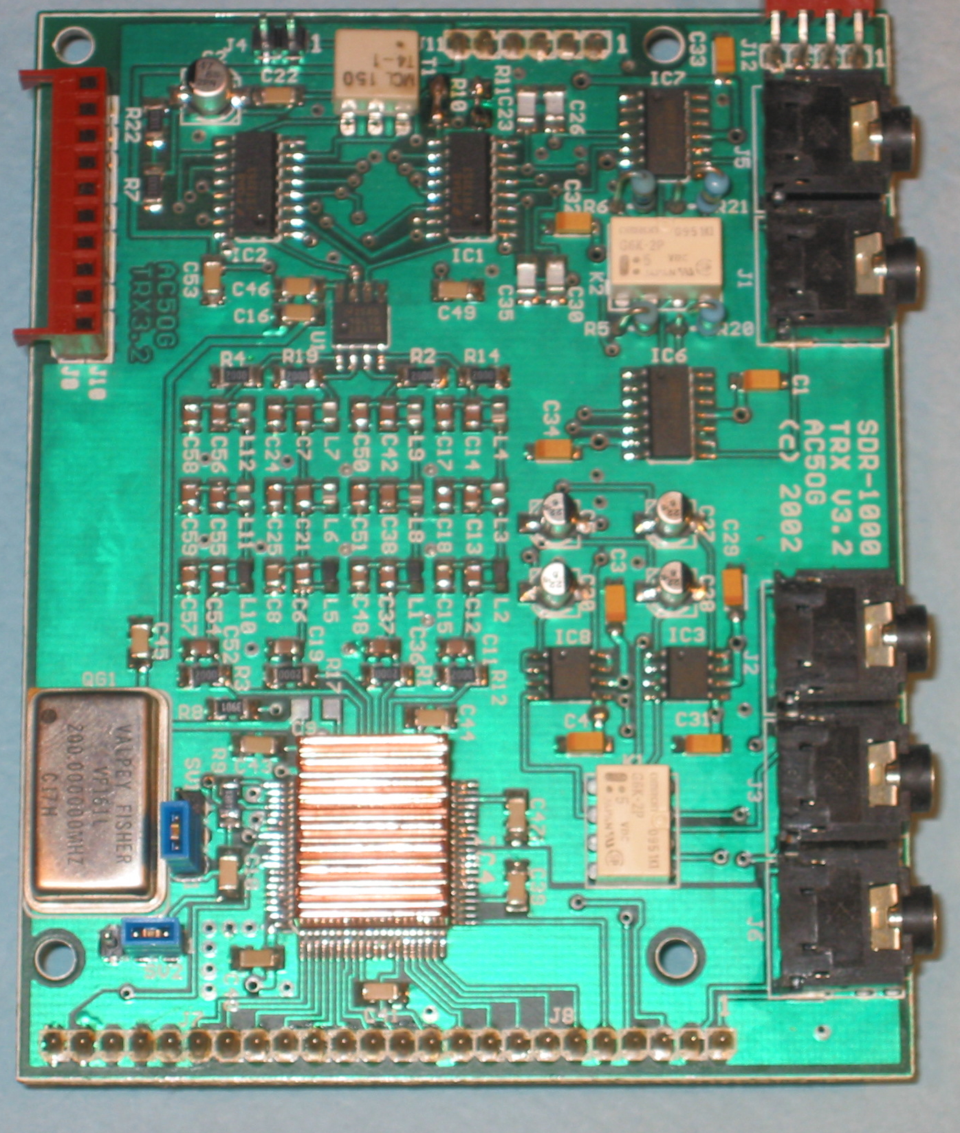
> > The second mistake is you need a low pass filter on each
> differential
> > output, 4 total in the case of the 9854 .... here's a picture of
> the
> > final design of the SDR-1000 and on the left, just above the
> > heatsinked 9850 you can clearly see the 4 filters
> > http://www.tracey.org/wjt/sdr1k/sdr-board-pics/trx-top.jpg
> >
> > If these things aren't corrected you will not get a 90 degree
> > quadrature output, or anything even close enough to be software
> > corrected, which sounds exactly your situation now
> >
> > I have a schematic of a working design using a MAX9172 which is
> > Maxim's version of the chip Gerald uses and is 100% compatable ...
> My
> > low pass filter is different than others (After numerous
> simulations
> > I'm convinced an elliptic filter is a poor choice for low Q surface
> > mount inductors and a Chevyshev low pass is better using surface
> mount
> > inductors. If you use higher Q [and much larger} inductors then the
> > Elliptic makes sense) but you can just substitute 2 more of the low
> > pass filters you already have and you can see how to correctly feed
> > them to the output amps
> >
> > If you are indeed using the LVDS amps like in the QEX article and
> > it's OK with Alberto I can upload the schematic and a picture of my
> > circuit laid out on a section of SMT protoboard
> >
> > JR
> >
> > --- In [email protected], "jeanrenier2004"
> > <jean.taeymans@> wrote:
> > >
> > > Hi everyone,
> > >
> > > I am new to this discussion group, so I may comment about items
> that
> > > have been covered before, please bear with me.
> > >
> > > I am currently finishing an home build SDR receiver front end
> > > project (very much) based on Gerald Youngblood's design
> published
> > > back in 2003. It is based on an AD9854 IQ local oscillator and a
> QSD
> > > plus a pair of amplifiers, the whole being preceded by a set of
> HF
> > > filters.
> > > I have written a little application in VB6 in order to control
> the
> > > DDS frequency and the HF filter bank using the parallel port.
> > > Nothing fancy, just to run some tests.
> > > Currently I use the following set-up: the audio output of the
> SDR is
> > > connected to an SB Audigy SE sound card of my desktop PC (the
> laptop
> > > has no stereo audio inputs) which is running SDRadio (version
> 0.99),
> > > while the control part is connected to the parallel port of my
> > > laptop PC (the desktop having no free parallel port). It is bit
> > > awkward, but it OK for testing, I'll buy a LPT/PCI card for the
> > > desktop one of these days.
> > >
> > > SDradio works great, it is a really remarkable piece of
> programming,
> > > good demodulation in AM and SSB (I did not try NBFM yet). The
> low
> > > frequency noise, some 3kHz both sides of the 0Hz is very well
> > > visible (and audible), but can be avoided altogether by tuning
> > > SDRadio some 5...10kHz up or down.
> > >
> > > I have a problem though, for some reason I can not fully
> calibrate
> > > the skew of the SB Audigy board, both the phase and amplitude
> > > cursors should actually be set to some position outside their
> range.
> > > I did the same exercise with an old SB PCI128 board, this one
> can be
> > > calibrated all right within the range of the cursors.
> > > I prefer however to use the SB Audigy board, as it has the full
> 96dB
> > > dynamic range when used at 16 bit resolution, which is some 10dB
> > > more than the SB PCI128 board.
> > >
> > > Another thing that would be nice, is the possibility to set the
> > > centre frequency of the spectrum display of SDRadio by an
> external
> > > program, the little application in VB6 in my case. So that it
> would
> > > be possible to actually change the frequency including the
> spectrum
> > > display in one single GUI action. Maybe having some API on
> SDRadio
> > > or possbly a global variable that would be read by SDRadio.
> > >
> > > As I use to listen in on the digtal modes (RTTY, HF fax, ...) I
> use
> > > other programs such as Hamscope connected to the output of
> SDRadio.
> > > This is done by actually patching the analog signal from the
> line
> > > out of one sound board (the one with SDRadio) to the line in of
> the
> > > other sound board (the one with Hamscope). It would be nice if
> > > SDRadio would have some means to perform this on the internal
> > > digital signal, avoiding a DA and AD conversion.
> > >
> > > Thanks for any help or advise and all the best,
> > > Jean.
> > >
> >
>
YAHOO! GROUPS LINKS
- Visit your group "soft_radio" on the web.
- To unsubscribe from this group, send an email to:
[EMAIL PROTECTED]
- Your use of Yahoo! Groups is subject to the Yahoo! Terms of Service.