"Everything old is new again."
Now that I think about it, maybe the added solder is helping by doing
more than just transfer the heat. As the current, which is at least 100
amps, spreads from the copper to the solder, the solder will heat up
which is exactly what we want.
Ed

On 7/26/2012 9:19 AM, Ron Ward wrote:
Hi ED:
Good point but I guess that it's all resistance heating and copper is
about 10 times more conductive than steel and the contact surface area
is quite small. Anyway, it has worked for me several times in the past.

I did a search at the ARRL website on crystal grinding and found two
articles that may interest you!
QST July 1963 page 75 "Removing Hermetically-Sealed Crystals" and
QST March 1963 pages 30,31 "Grinding Surplus Hermetically sealed
Crystals".

I didn't know that these articles existed until I did the search. Talk
about re-inventing the wheel!

Ron

-----Original Message-----
From: [email protected] [mailto:[email protected]] On
Behalf Of Ed Palmer
Sent: Thursday, July 26, 2012 12:43 AM
To: Discussion of precise time and frequency measurement
Subject: Re: [time-nuts] 5MHz ocxo

I'm not the original poster with the dead oscillator, but I have done
this in the past ( and will again in the future, I'm sure).  I'm
definitely going to try this idea.  I have both models of soldering gun
as well.  The bigger one is Model D550 and is rated at 200/260 watts.  I

think that's the one to use.  As you say, you want to work fast and the
larger one will do that.  I'm a little surprised that wrapping the wire
around a metal case and using solder to improve the heat transfer
doesn't more or less short out the loop and reduce the heat generated on

the side of the loop opposite to the connection points.

Ed


On 7/25/2012 11:55 PM, Ron Ward wrote:
Hi:
I have two. Both are made by Weller. The first one is rated for
100/140
Watts and works well for disassembling soldered HC-6U crystals without
damaging them. The second one is at least 250 watts maybe as high as
300
Watts. It is old and the label is missing. It has two lamps for
illumination. I feel that if you make the wire tight aginst the solder
area of the case that the 100/140 watt gun would work okay. Be sure to
tin all of the contact area of the wire that is wrapped around the
case's soldered junction. The non-contact area of the wire may be left
to oxidize and will act like an insulator making the tined area
hotter.
Fresh rosin core solder is easier to work with. Solder braid is also
very helpful to clean up the groove after the top of the case comes
off.
Be sure to ware safety glasses or goggles. Not much solder is released
but I wouldn't take any chances!
Also you might try both #12 and #14 as I don't know the current rating
of your soldering gun. The resistance of going to #12 wire is
compensated by the longer length for larger cases. I have never tried
Chip Quick but it could also be helpful. You could have a friend
preheat
the case with a large soldering iron if extra heat is required. I like
the soldering gun because it makes for a nice clean job when finished.
You will want to work fast so as not to heat damage the oscillator's
components.
Ron

-----Original Message-----
From: [email protected] [mailto:[email protected]]
On
Behalf Of Ed Palmer
Sent: Wednesday, July 25, 2012 8:28 PM
To: Discussion of precise time and frequency measurement
Subject: Re: [time-nuts] 5MHz ocxo

I haven't heard of that trick before, but it sounds interesting.
What's
the wattage of your soldering gun?

Ed


On 7/25/2012 6:41 PM, Ron Ward wrote:
Hi:
If you want to de-solder the case, I have had success taking some #12
or #14 bare copper wire ( standard solid conductor house-wiring stripped
of the PVC insulation ) and wrapping it tightly around the base just
above the soldered junction. The wire is installed in my soldering gun
just like a new soldering gun tip. Add just a little solder to help in
heat transfer. Be careful as it will get really hot. I hold the top with
a weird set of very long needle nose pliers. They are small enough that
they don't act like much of a heatsink. You could fabricate one out of
wood. They would be disposable.
I hope this helps,
Ron

-----Original Message-----
From: [email protected] [mailto:[email protected]]
On Behalf Of Paul Flinders
Sent: Wednesday, July 25, 2012 2:59 PM
To: Tom Miller; Discussion of precise time and frequency measurement
Subject: Re: [time-nuts] 5MHz ocxo

On 25/07/12 22:27, Tom Miller wrote:
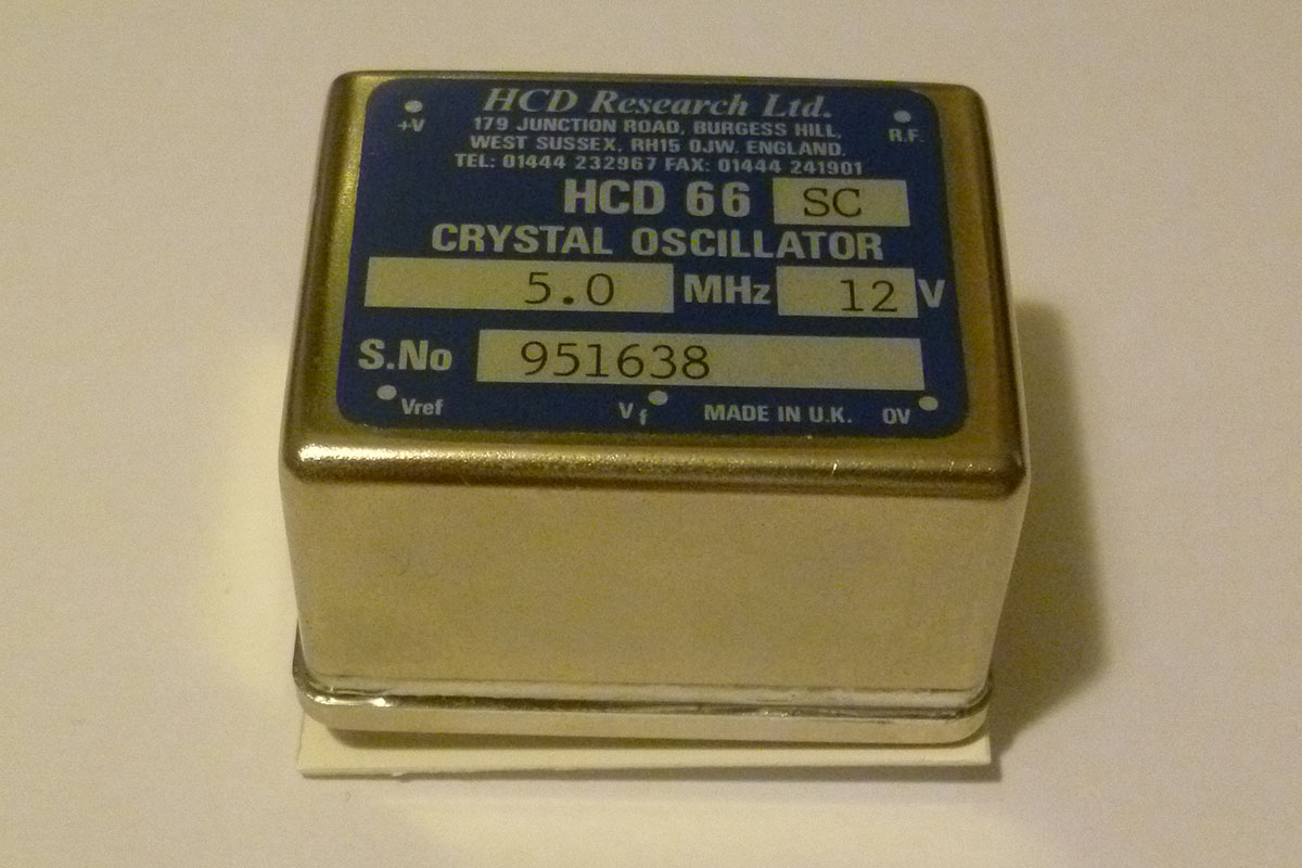
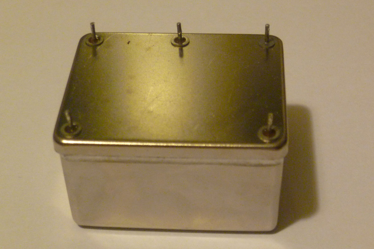
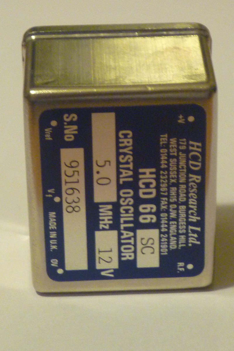
Can you post up a few pictures of the oscillator?

There have been people that have opened these up and repaired them.
If you feel not up to it, why not see if someone on this group can help.
Repairing it will eliminate a lot of searching.
Pictures at

http://www.wild-pc.co.uk/images/P1000981.jpg
http://www.wild-pc.co.uk/images/P1000982.jpg
http://www.wild-pc.co.uk/images/P1000983.jpg

Apologies for slightly poor quality.

It's fully soldered at the base - possibly wasn't done in one go but
I
suspect would all have to be heated to get it apart - I have an SMD
style hot air gun but it couldn't tackle that job.

If anyone is able to repair it I'd certainly be interested.
_______________________________________________
time-nuts mailing list -- [email protected]
To unsubscribe, go to
https://www.febo.com/cgi-bin/mailman/listinfo/time-nuts
and follow the instructions there.


_______________________________________________
time-nuts mailing list -- [email protected]
To unsubscribe, go to https://www.febo.com/cgi-bin/mailman/listinfo/time-nuts
and follow the instructions there.
_______________________________________________
time-nuts mailing list -- [email protected]
To unsubscribe, go to https://www.febo.com/cgi-bin/mailman/listinfo/time-nuts
and follow the instructions there.