Ooh err, whoops, and oh dear !!

Arthur, I've only just had a chance to look at your latest photos, and
unless I've really got my wires crossed, if you'll pardon the  expression:-),
your links on J5 are not shown on pins 2, 10, 12, and 15,  but on pins 4, 6,
11, and 13.

As far as I'm aware the numbering from the front of that connector as shown
 starts in the top right hand corner and every row is numbered right to
left.
That's certainly how mine are numbered anyway, and I wired them
accordingly, and it worked, so where the heck does that leave us now?:-)

It might explain of course why I could dispense with most of your interface
 but heaven knows what I've actually got strapped together!

Another "interesting" thing I noticed, once the Ref-1 unit is up and
running I can pull the plug from J5 and it keeps on going, to start with at
least anyway.
I pulled the plug on one unit to fit its cover and aside from the standby
light starting to flash, the ON light remained on and the outputs remained
enabled. It might have shut down if left like that but I haven't tried that
yet.

Next trick I think I'll try with just pin 3 grounded and go from  there.
Which raises the next question, are the connections to pins 3 and 4
actually connected to what I think are 3 and 4 or do I have that different  too?

Regards

Nigel
GM8PZR


In a message dated 02/11/2014 01:27:18 GMT Standard Time,
[email protected] writes:
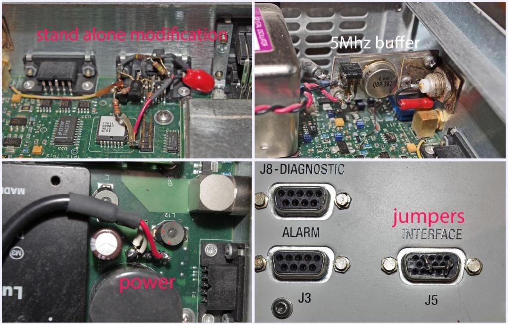
Keep in  mind that I made the modifications to my RFTG-u REF 1 almost
4 years ago  and the details of why I did what I did are kind of foggy
today. It was a  pure hack but I *believe* that the circuitry as well
as the jumpers were  required, or at least I thought so. The big problem
with getting something  like this to work is that after spending a lot
of time on it I generally go  on to the next project and as long as what
I did works, I forget about it  because it is a one of a kind thing. The
photo link below shows the 5Mhz  buffer amp I connected to the TP in
front of the oscillator that uses a  mounting bracket that is secured
by the BNC connector that outputs the  5Mhz. The 24V/2A power supply that
I mounted on the back connects across  the diode on the circuit board as
shown. The transistors and other  components of the modification that are
mounted free form on the back of  the J5 connector get the +5VDC from
the header directly in back of J5. The  wire on the left goes through an
existing hole on the circuit board to  connect to the fault LED.

I was hoping that someone else would  duplicate the modification just to
reassure me that what I did wasn't black  magic. It looks like Nigel is
doing just  that-thanks.


http://i906.photobucket.com/albums/ac262/rjb1998/RFTG-uREF1_zps546e4c82.jpg
_______________________________________________
time-nuts  mailing list -- [email protected]
To unsubscribe, go to
https://www.febo.com/cgi-bin/mailman/listinfo/time-nuts
and follow the  instructions there.

_______________________________________________
time-nuts mailing list -- [email protected]
To unsubscribe, go to https://www.febo.com/cgi-bin/mailman/listinfo/time-nuts
and follow the instructions there.