Oh well, as was said before, one of the biggest problems working on
something like this can be the watching and the waiting, but  sometimes it
might
be worth the wait, and sometimes having a bit  of luck thrown in along the
way can be quite handy too:-)

As mentioned earlier, I'd implemented Arthur's circuit but left the  fault
light connection as a flying lead to be switched manually.
Originally, after the unit started up with the fault light on, I  found
that when the light eventually went out I had to switch this input to  ground
to enable the outputs.
As a follow up though it did seem  worth trying with this connection
grounded all along, just  out of curiosity of course, and it also seemed to
start
up just fine like  that:-)

A quick look at the circuit showed that this left the wire to J5 pin 3 also
 grounded all along and a question hanging over what was happening to J5
pin  4.
In the static condition there's approx 1.5 volts across the 470 ohm
resistor but it would normally get pulsed at some time in the  proceedings.
However, with the fault light connection permanently grounded it  didn't look
like
this was going to be exactly hyper active either.
So the next step was to directly ground J5 pin 3 and for J5 pin 4 to be
grounded via the 470 ohm resistor, without knowing what was driving it from
inside the unit a direct short could have been asking for trouble, and to
dispense with the transistor circuit.

And guess what, that worked too:-)

So it would seem that whilst all the blinking of lights and assorted
handshaking and negotiating are necessary to sort out the status  quo between
two
boxes, it might be a bit less complicated  with just the one after all.

By way of confirmation I wired up another Ref-1 unit, straight out of the
box and previously unused, powered it up, and left it to get on with it.
After the quick LED test sequence it started out with the "No GPS" and
"Fault" lights on permanently and the "STBY" and "ON" lights off.
Just about 75 minutes later the "No  GPS" and "Fault"  lights went out, the
"ON" light came on permanently, and we  had 15MHz and 1PPS outputs from
that one too:-)

One as yet unexplained difference between the two units is that the first
one performed in a similar fashion but the "ON" light was flashing from
shortly after the initial test sequence, even whilst the "No GPS" and  "Fault"
lights were still on, and it remained flashing after they  went out, and so
far has never been on permanently at all.
I've since put that one back on test and it's still behaving in the  same
way but still booting up ok just the same.
Whether this indicates some sort of fault condition in the first unit,
running just the bare board might have been asking for trouble, or some  form
of randomness in behaviour such that these results aren't entirely
predictable, I don't know, but so far both seem to be consistent in their own
fashion and two out of two isn't a bad start:-)

It would be appreciated if others could try this too, confirmation  that it
works elsewhere would be great, and knowing it was a pure fluke and  never
to be repeated could be quite useful too:-)

To recap, this is a Ref-1 unit with onboard GPS and what I'm doing is to
make the following connections to the J5 "Interface" connector, using  a
small plug in breadboard as a temporary junction box.....

Pins 2, 10, 12, and 15 of J5 are connected together but not connected to
anywhere else.

Using a ground connection taken from J5 pin 8, J5 pin 3 is connected
directly to ground, and J5 pin 4 is connected to ground via a 470ohm resistor,
again with no other connections.

That's it, after power up and an appropriate delay, assuming my results are
 repeatable, the outputs should be enabled and away we go.

Uh oh, after writing the above it occurred to me as an afterthought  that I
should probably also check what might happen if J5 pin 4 was  disconnected
altogether, so I removed the 470ohm resistor from the original  unit whilst
it was running and the voltage on pin 4 rose to just over 4.7  volts, the
"ON" light continued to flash.....
and the outputs remained enabled.
After that I just have to try it from start up, and also to try it on the
second unit too, who needs sleep anyway?:-)

The first one did start up ok with J5 pin 4 disconnected and whilst
waiting for that to come live I've made up a plug adapter using an old VGA
patch
cable and now have the second one on test again and waiting to see what
happens  this time.

And there you have it, finally, the other one up and running again  also:-)

I happened to be watching this one this time as it went live and the "ON"
light flashed once before coming on permanently, perhaps not very
significant  but just thought I'd mention it anyway.

So that's it folks, after all this it would now seem that all that's
needed to enable a Ref-1 unit stand alone is to link together J5 pins 2, 10,
12,
and 15, and to ground pin 3 to pin 8, and then just hang around for hours
and  hours on end with yer fingers crossed:-)
I don't know if it's possible to monitor the J8 Diagnostic port whilst
waiting for it come live, that would at least give a better idea of what's
going  on, but I deliberately avoided any other connections whilst trying this
out so  it's possible that might be inhibited also.

Anyway, apologies for all the waffle, I've been topping this up as I  go
along whilst surviving on coffee and getting a bit groggy in the process,
it's 0730 here now and no sleep yet, but once I'd had my first encouraging
results there was no way I could just go to bed and leave it:-)

Regards

Nigel
GM8PZR


In a message dated 02/11/2014 02:00:23 GMT Standard Time, [email protected]
writes:
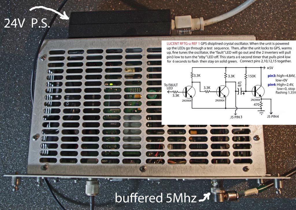
Hi

I’ve watched the two boxes fire up. They spend a bit of  time blinking
lights on this one and then on that one. From watching the  “dance”, I think
that the transistor delay circuit (or something like it) is  indeed needed.
There are multiple ways the delay and sequencing could be  implemented. A
cheap 5V PIC is certainly one way to do it. With no voltage  coming out on the
connector doing a purely external solution probably is going  to require
external power. I think I’d at least bring that out on one of the  many unused
alarm pins.

Bob

> On Nov 1, 2014, at 9:52 PM,  GandalfG8--- via time-nuts
<[email protected]> wrote:
>
>  Hi Bob,
>
> I understand the consequences of not modifying the  unit but, having done
so
> and having a REF-1 unit running stand alone,  I was just commenting that
I
> wasn't  sure whether or not it was  necessary to implement all of
Arthur's
> modification in order to  enable the basic functionality, or whether some

> part of it  might be purely to control the indicators.
>
> As a follow on  from that I was wondering whether or not it might  be
> possible  to achieve a similar result, at least to the point of just
making it
> functional, just by cross linking some of the out and return  paths,
"faking"
> it without the need for an additional powered  interface if you  like,
not for
> any other reason than it might  then be possible to make  a plug in
> modification that could be  fitted without needing to  open the box.
>
> Regards
>
> Nigel
> GM8PZR
>
>
>
>
> In a  message dated 02/11/2014 00:19:57 GMT Standard Time, [email protected]

> writes:
>
> Hi
>
> If you:
>
>  1) Do not have two units (Ref 0 and Ref  1)
>
> — and  —
>
> 2) Do not “fake out” the slave detect (= use the   mod)
>
> Then the unit you have will not:
>
> 1)  Enable the pps  out
>
> 2) Enable the 15 MHz out
>
> It will try to disciple the OCXO,  but you won’t be able to see  any
result
> of that.
>
> Bob
>
>
>> On  Nov 1, 2014, at 7:05 PM, GandalfG8--- via time-nuts
> <[email protected]>  wrote:
>>
>> Hi  Anthony,
>>
>> It's a new circuit that  has to be  inserted, which is what I've done,
but
>
>> I'm not  sure  whether or not it's strictly necessary for the unit to
>  function
>> or  whether it's just there to get the lights  sequencing properly and
>> perhaps all  that's needed for  basic functionality are just the  links.
>>
>> I'm  leaving well alone for now to let the oscillator  run overnight but

>> will try it again tomorrow with just the  links and see what  happens.
>> I'm also hoping to get some idea of the  between  unit signalling,
> although
>> I only have Z3811s  I'm  hoping, with the boards being an almost
> identical
>> match, that  what goes one way should be matched by what  comes the
other.
>>
>> Regards
>>
>> Nigel
>> GM8PZR
>>
>>
>>
>> In a message dated 01/11/2014 22:41:09 GMT Standard Time,
> [email protected]
>> writes:
>>
>>  I wasn't  clear  from the photo whether the circuit was a
representation
> of
>> what is  on  the board, and  you just had to connect the pins listed
> together,
>>  or whether  this was a new circuit that had to be  inserted.   Sounds
like
>> the  latter?
>>
>>  Anthony
>>
>> -----Original Message-----
>>  From:  time-nuts  [mailto:[email protected]] On Behalf Of
>> GandalfG8--- via  time-nuts
>> Sent: Saturday,  November 01, 2014  4:04 PM
>> To:   [email protected]
>> Subject: Re: [time-nuts]  Lucent KS-24361,  HP/Symmetricom  Z3809A,
> Z3810A,
>> Z3811A,   Z3812...
>>
>> Well, I'm happy to report that   Arthur's  modification does do the
trick,
>> although I don't  know why as I  don't  have any data for the interface
>  as yet.
>> I daren't  disturb the 15 pin  connector right  now as this  Z3811A PCB
is
>
>> still out of its case  and  connected to a breadboard  with  wires just
>  pushed
>> into the sockets, and  for the same reason I   don't have  any computer
>> connection at the  moment   either.
>>
>> My implementation isn't  quite as described, in that  I've not  made a
>>  connection to the fault LED but am just  manually pulling that  input
> high and low
>> on the breadboard with   another wire link as required.
>> Whether  or not this is part  or  all of the reason that my green "on"
> light
>> is  flashing  rather than steady I don't know, but I am  seeing the 1PPS
> and
>> 15MHz  outputs and the 15MHz  looks to be conditioning ok.
>>
>> Aside from the 5   volt supply, which I'm picking off from pin 5  of the
>> header  between u33 and  U34, and the aforementioned fault  LED
>  connection, all
>> the  other  connections can be made  to  J5 externally and could be
housed
> in a
>> 15   way  shell along  with the switching circuits.
>>
>> I'm still hopeful that  some  cross linking of the  right pairs might
>> achieve the  same result  without  the extra circuitry, so "all" that
> needs to   be
>> done now is just to  identify the right  pairs:-)
>>
>> At least with it up and running it  should  be easier to check  out some

> of
>>  the inter-unit signalling.
>>
>> Thanks  Arthur, your  efforts are much  appreciated.
>>
>>  regards
>>
>> Nigel
>> GM8PZR
>>
>>
>>
>>
>>
>>
>>
>> In  a message dated  01/11/2014 15:25:02 GMT Standard  Time,
> [email protected]
>> writes:
>>
>> For  those who missed it, Arthur's  post is  at
>>  https://www.febo.com/pipermail/time-nuts/2010-June/047825.html  and
the
> photo  is at
>>
>
http://i906.photobucket.com/albums/ac262/rjb1998/RFTG-uREF1photo1_zps87c505ca.jpg
>>
>> Anthony
>>
>>
>>
>>
>> -----Original   Message-----
>> From:  time-nuts  [mailto:[email protected]] On  Behalf  Of
> Arthur
>> Dent
>> Sent: Friday, October 31, 2014  9:20  PM
>> To:   [email protected]
>>  Subject: [time-nuts] Lucent KS-24361,   HP/Symmetricom  Z3809A,
Z3810A,
>> Z3811A, Z3812A GPSDO  system
>>
>> Bob  Stewart bob at  evoria.net
>> ?? ?   I have both of my units sitting on the  bench. I found that  I
> needed
>> to connect them together to get the REF1   unit to come  out of standby
?
> . ??
>>
>> Bob Camp kb8tq at   n1k.org
>> ??I suspect  that somebody will have  to figure out what  the 15  pin
>> connector / jumper is doing. On previous RFTG   units  there was a way
to
> re-wire
>> the crossover interface  to  fake out the slave  detect process.  That
> would  let
>> you run  a single GPS equipped box and have it   behave  correctly.
> Without
>> the fake wires  trick none of them played nice  without  the  slave
being
>> present ?
>> .   ??
>>  ++++++++++++++++++++++++++++++++++++++
>> Reposting what I  had   posted  over a week ago, in case you missed it ?
 .
>>
>> Arthur Dent  golgarfrincham  at gmail.com  Wed Oct 22 13:59:48 EDT  2014

> ??
>> ?
>> Way back on Fri Jun 11  16:48:43  UTC 2010 I posted  about using one of
>> these units I had modified   but  at the time there wasn't a single
person
> who
>>  was  interested. I have been using  the RFTG-u REF1 since then and  it
is
> a
>> nice unit. The modifications I added   (including a power  supply -see
> photo)
>> allows  the lights to cycle through  their  normal sequence on  warm-up
> and the
>> second unit  isn't needed at all ?  .   ??
>>
>> -Arthur
>>  _______________________________________________
>> time-nuts   mailing list -- [email protected] To unsubscribe, go to
>>  https://www.febo.com/cgi-bin/mailman/listinfo/time-nuts
>> and   follow  the  instructions   there.
>>  _______________________________________________
>>  time-nuts   mailing  list -- [email protected] To unsubscribe,  go to
>>  https://www.febo.com/cgi-bin/mailman/listinfo/time-nuts
>> and   follow  the  instructions  there.
>>
>>  _______________________________________________
>>  time-nuts   mailing list -- [email protected] To unsubscribe, go  to
>>  https://www.febo.com/cgi-bin/mailman/listinfo/time-nuts
>> and  follow  the  instructions there.
>>
>>  _______________________________________________
>> time-nuts mailing  list  -- [email protected]
>> To unsubscribe, go to
> https://www.febo.com/cgi-bin/mailman/listinfo/time-nuts
>>  and follow the  instructions there.
>
>  _______________________________________________
> time-nuts mailing list  -- [email protected]
> To unsubscribe, go to
https://www.febo.com/cgi-bin/mailman/listinfo/time-nuts
> and follow the  instructions  there.

_______________________________________________
time-nuts mailing list -- [email protected]
To unsubscribe, go to https://www.febo.com/cgi-bin/mailman/listinfo/time-nuts
and follow the instructions there.