Hi

Well I for one am not getting at all bored at seeing what you are doing. I find
it very encouraging that somebody is sharing all the ins and outs of figuring
out what’s going on. Far to often we simply get the end result and not much
detail (I for one have been rightly criticized for that within the last day or
two …). Keep up the information stream. Keeping the information on the list
puts it into the archives so it can be dug up by everybody.
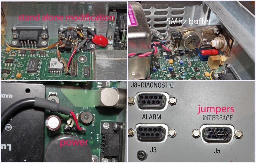
Bob

> On Nov 2, 2014, at 9:44 AM, GandalfG8--- via time-nuts <[email protected]>
> wrote:
>
> Oh well, and perhaps not too surprisingly, the J5 pin 3 to ground option on
> its own was not that much of a raging success.
>
> However, the unit did eventually come up indicating "Standby", and at that
> point pulling out the pin 3 to ground link and inserting the previously
> made up  plug switched it into "On" mode and up came the outputs.
>
> I'm sure everyone is getting a bit tired of hearing me going on  about
> this, and it's hard to know what else to add other than to say there seems
> to
> be more than one option that will do the trick, but my wired plug as
> previously described, and wired according to the starting in the top right
> hand
> corner numbering scheme, does, for me at least, seem to work every time,  so
> I
> think I'll just stick with that and quit whilst I'm ahead:-)
>
> Regards
>
> Nigel
> GM8PZR
>
>
> In a message dated 02/11/2014 01:27:18 GMT Standard Time,
> [email protected] writes:
>
> Keep in  mind that I made the modifications to my RFTG-u REF 1 almost
> 4 years ago  and the details of why I did what I did are kind of foggy
> today. It was a  pure hack but I *believe* that the circuitry as well
> as the jumpers were  required, or at least I thought so. The big problem
> with getting something  like this to work is that after spending a lot
> of time on it I generally go  on to the next project and as long as what
> I did works, I forget about it  because it is a one of a kind thing. The
> photo link below shows the 5Mhz  buffer amp I connected to the TP in
> front of the oscillator that uses a  mounting bracket that is secured
> by the BNC connector that outputs the  5Mhz. The 24V/2A power supply that
> I mounted on the back connects across  the diode on the circuit board as
> shown. The transistors and other  components of the modification that are
> mounted free form on the back of  the J5 connector get the +5VDC from
> the header directly in back of J5. The  wire on the left goes through an
> existing hole on the circuit board to  connect to the fault LED.
>
> I was hoping that someone else would  duplicate the modification just to
> reassure me that what I did wasn't black  magic. It looks like Nigel is
> doing just  that-thanks.
>
>
> http://i906.photobucket.com/albums/ac262/rjb1998/RFTG-uREF1_zps546e4c82.jpg
> _______________________________________________
> time-nuts  mailing list -- [email protected]
> To unsubscribe, go to
> https://www.febo.com/cgi-bin/mailman/listinfo/time-nuts
> and follow the  instructions there.
>
> _______________________________________________
> time-nuts mailing list -- [email protected]
> To unsubscribe, go to https://www.febo.com/cgi-bin/mailman/listinfo/time-nuts
> and follow the instructions there.

_______________________________________________
time-nuts mailing list -- [email protected]
To unsubscribe, go to https://www.febo.com/cgi-bin/mailman/listinfo/time-nuts
and follow the instructions there.