Michael Schippling ha scritto:
> The photo still doesn't help much...
> I'd like to see how the connector is mounted
> to the board and how the wires are then connected,
> but probably would have to be able to handle the
> actual object...
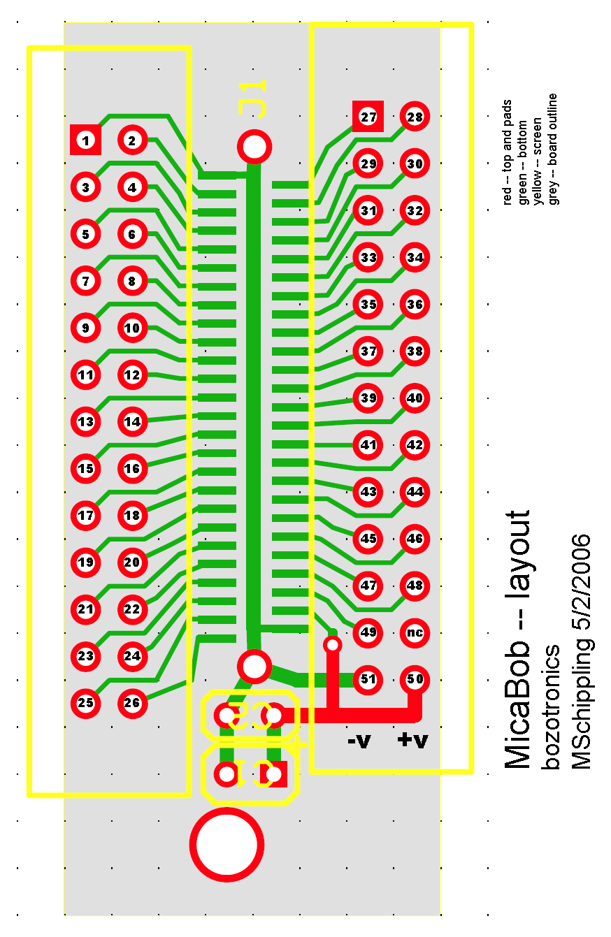
The connector is mounted to the board with only the solderings of the
VCC/ADC1/GND pins. They sustain the connector firmly.

> Anyway according to my layout, power should be coming
> off of one end of the connector and the pin 42 ADC input
> is about 1/3 of the way in from the power end. So the
> wires coming out of the top of the card seem to be
> in inappropriate locations. Here's my layout:
> http://www.etantdonnes.com/Motes/MicaBOB/micaBOB_layout.png

This photo is a zoom, so you can count the pins:
http://img267.imageshack.us/img267/8161/dsc0750cj.jpg
The connection seems right.

> I meant that if you were successful in reading the sensor
> board, where the Photo/Temp input is on ADC1, then there must
> be something wrong with your break-out-board.

One moment... Hence in IRIS mote the ADC1 channel is connected to
Photo/Temp? I can't connect a potentiometer?

> Especially if you
> use the same mote program in both cases. Trying the whole
> thing again with a bare connector and getting your power directly
> from the battery to minimize connector diddling might help point
> you in the right direction.
>
> MS

Thanks Michael.

Greetings,
--
Francesco Ficarola <francesco.ficarola_at_gmail_dot_com>
[GPG KeyID: 0xDBA99D92]
![]() signature.asc
signature.asc
Description: OpenPGP digital signature
_______________________________________________
Tinyos-help mailing list
[email protected]
https://www.millennium.berkeley.edu/cgi-bin/mailman/listinfo/tinyos-help