The previous photo from the top of the board, looked like the
red and blue wires (which I thought were the power) were
coming from the middle of the board and there were two black
wires coming from one end. That's what I meant about having
to actually be there to see what was what....
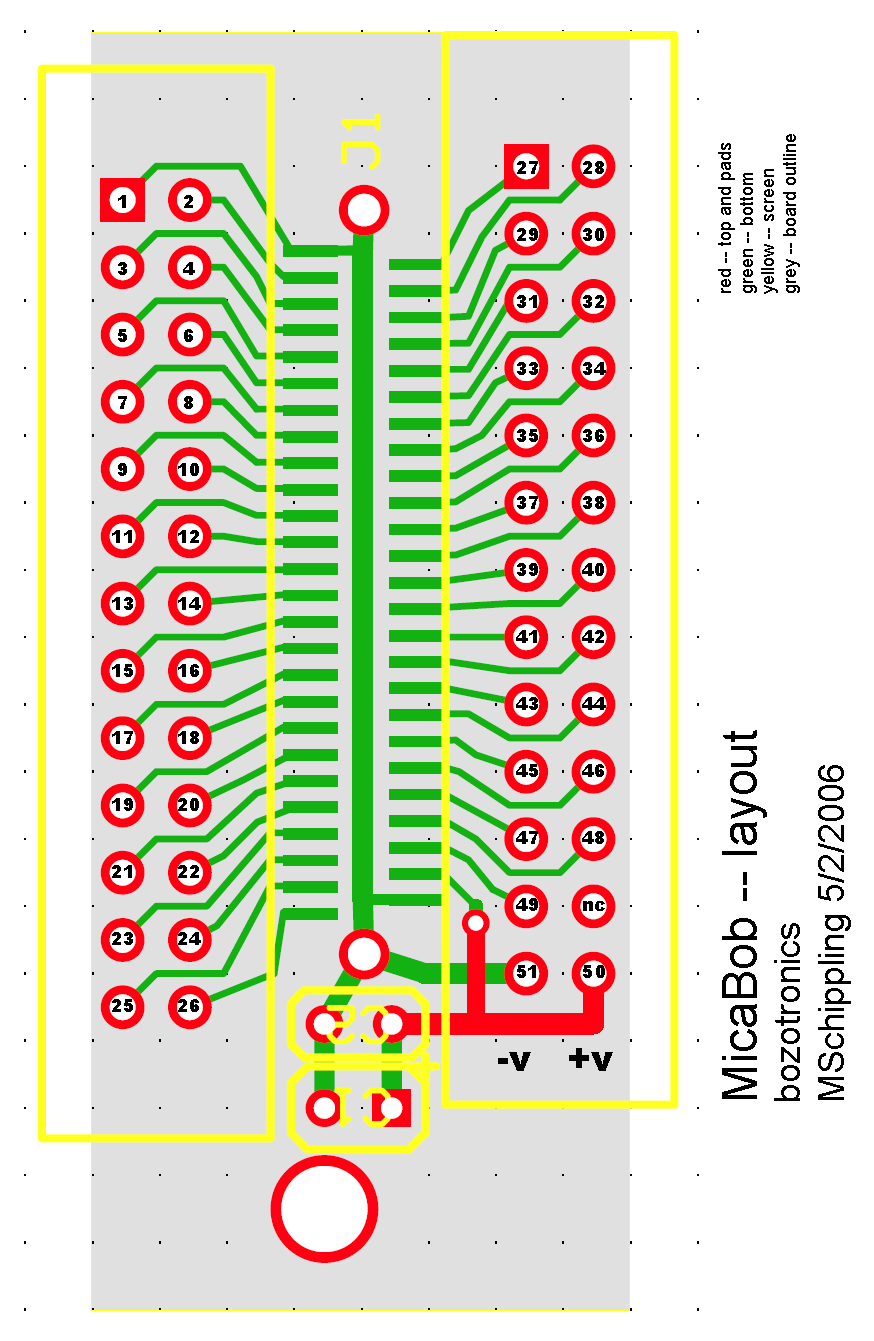
Anyway did you try the single wire on a bare connector thing?

The Photo/Temp sensor is on the micasb sensor board -- the
MTS300 or 310...I keep loosing track of the part numbers.
I think the MDA300 also has them, but can't find any actual
schematics.

The only ADC connections on the mica2,z boards themselves
are Voltage at ADC7 and RSSI at ADC0. I presume that the
IRIS board is the same, and also that it has the same
52 pin expansion layout.

I think you stated that you were able to read the sensor-
board Photo/Temp correctly, without Voltage value interference.
And also that you were able to read Voltage when there was no
sensor board attached. This leads me to believe that the
problem is in the element that changes: your  break-out-board.

Probably the thing to do at this point is back-up to the
beginning and try everything again, changing only one element
  -- both software and hardware -- at each step. Debugging
this stuff by remote control is basically impossible though.

MS


Francesco Ficarola wrote:
> Michael Schippling ha scritto:
>> The photo still doesn't help much...
>> I'd like to see how the connector is mounted
>> to the board and how the wires are then connected,
>> but probably would have to be able to handle the
>> actual object...
>
> The connector is mounted to the board with only the solderings of the
> VCC/ADC1/GND pins. They sustain the connector firmly.
>
>> Anyway according to my layout, power should be coming
>> off of one end of the connector and the pin 42 ADC input
>> is about 1/3 of the way in from the power end. So the
>> wires coming out of the top of the card seem to be
>> in inappropriate locations. Here's my layout:
>> http://www.etantdonnes.com/Motes/MicaBOB/micaBOB_layout.png
>
> This photo is a zoom, so you can count the pins:
> http://img267.imageshack.us/img267/8161/dsc0750cj.jpg
> The connection seems right.
>
>> I meant that if you were successful in reading the sensor
>> board, where the Photo/Temp input is on ADC1, then there must
>> be something wrong with your break-out-board.
>
> One moment... Hence in IRIS mote the ADC1 channel is connected to
> Photo/Temp? I can't connect a potentiometer?
>
>> Especially if you
>> use the same mote program in both cases. Trying the whole
>> thing again with a bare connector and getting your power directly
>> from the battery to minimize connector diddling might help point
>> you in the right direction.
>>
>> MS
>
> Thanks Michael.
>
> Greetings,
_______________________________________________
Tinyos-help mailing list
[email protected]
https://www.millennium.berkeley.edu/cgi-bin/mailman/listinfo/tinyos-help