You make a good point.  Three phase rectification and filtering is far easier
than single phase and that might be his reasoning.  I suspect that sooner or
later he will begin using power factor correction electronics to get the
present relatively poor value of .5 up to standards.
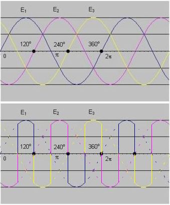
The present poor pf could be due to triac timing or perhaps rectification and
filtering where the peak input current from the power line is large.  I suspect
that Rossi is working with a rectified and then filtered source for his
internal power electronics.  This allows him to adjust the resistor drive
waveforms to shapes that optimize performance.

The power factor with a rectification system suffers for a good reason.  The
bridge diodes are only conducting for a relatively short part of the cycle and
that generates large harmonic currents in the primary circuit.  As I have
posted earlier, only the fundamental component of the primary current waveform
can extract power from the sine wave source.

 DC or harmonic currents flowing from the wall socket contribute to the RMS
current reading of the measurements but can not extract energy from that
source.  I realize that this is difficult to grasp and has lead to plenty of
confusion in the recent dialogs.  This can be simulated in spice or calculated
by taking the integral of the product of the instantaneous voltage times
current from a source.  You will see that power due to harmonic currents
balances out over a fundamental voltage cycle.  This is an interesting exercise
for anyone that wants to look into the issue further.

Dave


-----Original Message-----
From: Rob Dingemans <[email protected]>
To: vortex-l <[email protected]>
Sent: Wed, May 29, 2013 11:05 am
Subject: Re: [Vo]:new hypothesis to confute regarding input energy in Ecat test


Hi,

On 29-5-2013 16:47, Berke Durak wrote:
> Using three phases you can get DC with decent ripple using only a
> handful of diodes.  The power never goes to zero, whereas it would go
> to zero 100 times a second if you were using a full-wave rectifier
> with single-phase input.  If the peak power required by the e-CAT is
> around 1 kW, then you would need caps supplying up to 1 kW.  We're
> talking ~100 µF caps rated at 350V supplying 3.5A.  Such large caps
> are difficult to find and it makes more sense to go with multiple caps
> in parallel to supply that current.  These caps would dissipate a
> couple watts each.  Temperature very quickly shortens the lifetime of
> aluminum electrolytic caps.  Hence, if you use them you reduce the
> reliability of your device, which could be a problem for the e-Cat.
> And the above assumes the peak power is 1 kW.

Here is an interesting circuit: http://www.nbtv.wyenet.co.uk/6-fasen.gif
with these voltage and current
http://www.nbtv.wyenet.co.uk/3-fasenspanning+stroom.jpg
It "converts" the three 50 Hz phases into one output of 300 Hz  :-) ,
which is a lot easier due to the smaller capacitor needed to be directed
into DC!

Kind regards,

Rob