Jason:
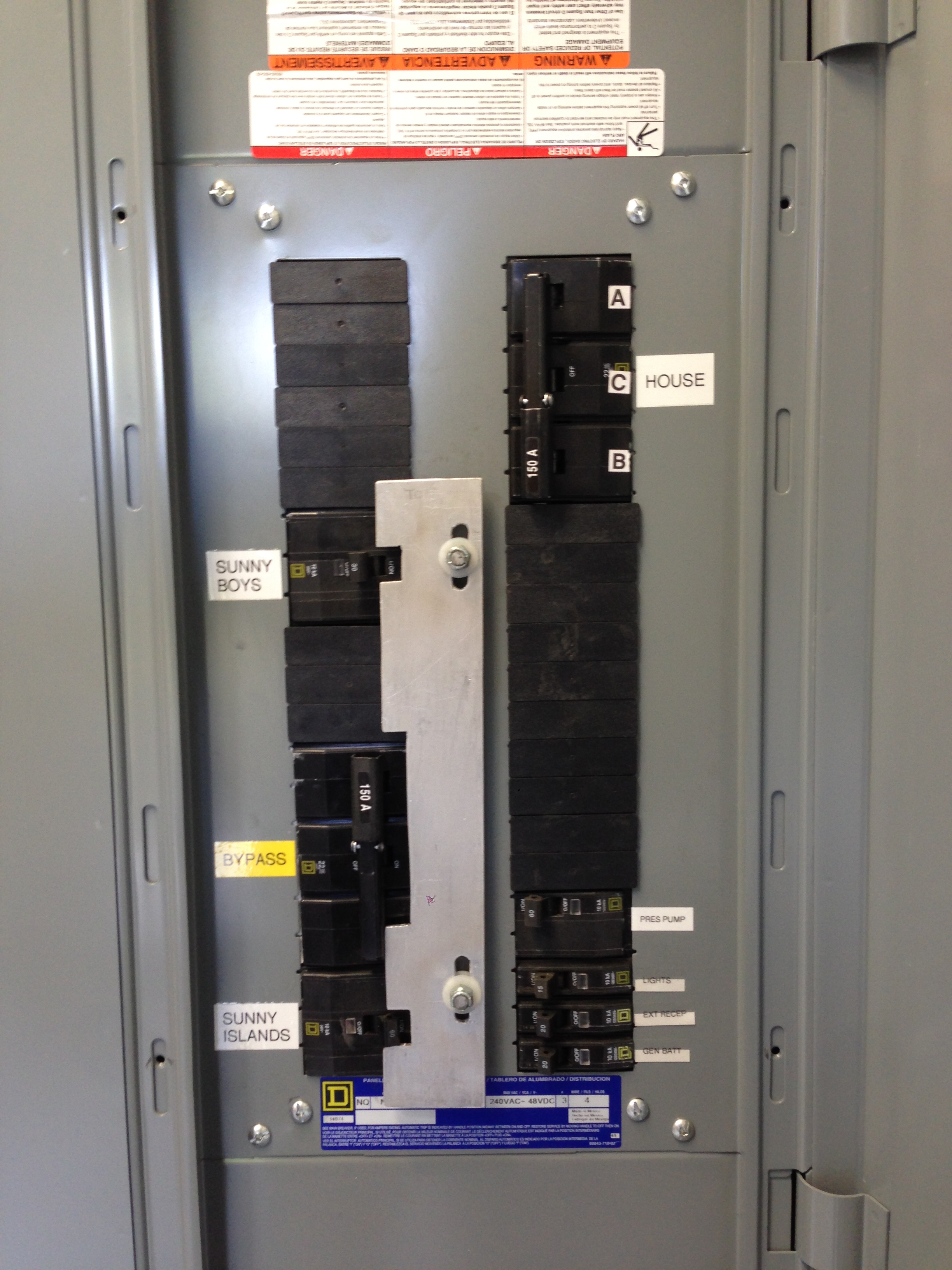
Replies below.


Miller Solar

17395 Oak Road, Atascadero, CA 93422

805-438-5600

www.millersolar.com

CA Lic. 773985


*From:* Jason Szumlanski [mailto:ja...@floridasolardesigngroup.com]
*Sent:* Wednesday, March 27, 2024 3:12 AM
*To:* will...@millersolar.com
*Cc:* RE-wrenches
*Subject:* Re: [RE-wrenches] Sol-Ark 15K AC Output


William,


Thanks for the information on grid peak shaving. That is what I thought
could be done. The description is a misnomer of sorts (like a lot of things
in Sol-Ark lingo). It's a bit hard to follow and not nearly well
enough documented, particularly with respect to parallel systems.  You are
welcome.  The Sol-Arc manual is not a great manual in any regards.


I follow what you are saying about using the 80A input breakers. The
problem I have is that you must set the generator kW to 36,000 in the
master inverter, not 9,000W in each inverter. The concept of "underrating"
the input breakers theorizes that each inverter will share the generator
pass-through equally. I do not know that to be the case. And what happens
if the three slave inverters have a fault or are turned off? That would
allow the single master to pass through the full generator supply.
Obviously this trips the 80A input breaker and protects the conductors, but
I feel that is a design deficiency when a single inverter is fully capable
of passing through all 150A.  You may be designing for an eventuality that
will never occur:  If the inverters fail then they should be repaired or
replaced.  While awaiting repair the bypass will keep your loads powered at
full capacity.


On top of that, I don't think the 80A output breakers are sufficient
because each inverter can peak shave 50A with inverter power from the
batteries. Add that to the theorized balanced 37.5A "grid" input, and you
are at 87.5A of possible throughput.  I am not sure why you are designing
to deliver more than the inverters will produce.  The generator support
function is intended to assist powering loads when the generator is
undersized.  I define that as the generator ampacity being less than that
of the inverter system.  The 36kVA generator is greater in ampacity than 4
Sol-Arc 15s.  You can turn the generator support function down or off in
the Sol-Arc.  I would recommend it be set to off for this project.  (If
there are to be occasional loads that are greater than the inverters can
deliver, like a welder or a car charger, with the plan I suggested you have
a generator-fed panel that can feed those occasional large loads with the
generator running.)


But assuming the 80A input/output concept works, other than a panelboard
with bolt on breakers, what low-cost load center allows you to fasten four
80A backfed breakers? If this is available, I could use a recommendation.
The load centers I am familiar with only have provisions for one fastened
backfed breaker.  I use to specify bolt-on panels for this but I came to
believe this is overkill.  QO breakers are held in place by the panel cover
that overlaps the breakers.  Other breakers are configured so the contact
points for the breaker bus are recessed.  You need to convince your AHJ
that this satisfies the requirement.  Part of the discussion should include
the point that off-grid systems are specialized and people that do not
understand them should not be working on them (or judging them-- is what I
tell inexperienced plan-checkers).


With respect to the bypass, I would usually use a DPDT switch to accomplish
this, Even for 400A bypasses, there seems to be a relatively cost effective
option in the Ronk 7416 (which to date I have not used). I get the concept
for smaller (<=100A) generators that you could use a generator interlock on
an off-the-shelf load center. But they typically only allow a single
backfed 2-pole breaker, whereas something like a Square D QO panel with a
backfed 150A breaker requires 4 spaces and is incompatible with the
interlock device.  Since bypass is an emergency condition, I sometimes
limit my bypass to 100 amps.  If you want full bypass ampacity you can
build an interlock to accommodate any size breaker.  Here
<https://millersolar.com/MillerSolar/Portfolio/Commercial/RM/Interlock.JPG>
is a photo of a large frame breaker being interlocked.  Here
<https://millersolar.com/MillerSolar/Portfolio/Commercial/RM/RM_Interlock.pdf>
is a design sketch exploring multiple interlock options.


Always, this is a great discussion and specific recommended equipment is
appreciated.


Jason Szumlanski

Principal Solar Designer | Florida Solar Design Group
NABCEP Certified Solar Professional (PVIP)
Florida State Certified Solar Contractor CVC56956

Florida Certified Electrical Contractor EC13013208


On Wed, Mar 27, 2024 at 12:33 AM William Miller <will...@millersolar.com>
wrote:

Jason:


Sol-Arc does provide generator support.  They call it “grid peak load
shaving” and it is described on page 22 of the manual.  Below is an excerpt.


*Error! Filename not specified.*


For those that may not be familiar with the concept of generator support,
here is how I describe it:  The inverter(s) are programmed for the
generator capacity.  If the generator is powering loads and the demand
exceeds that programmed generator capacity, the inverter can start
inverting and synchronize output to the generator to add power.  This is
only possible if battery charge levels are adequate.  In the Sol-Arc this
function can be adjusted or turned off.


Regarding my recommendations on wire sizing:  I may have done a poor job
describing how I see your project best approached.  Below is a diagram that
may do a better job.  Power flow is from left to right:


*Error! Filename not specified.*


If you follow what I am laying down, you can see there is no single
inverter or inverter wire that can pass or create more than 80 amps.  Ergo
#4 copper.  The money and time you save can easily purchase 8 80 amp
breakers.  If you look at Diagram 10 in the April 5, 2022 Sol-Arc manual
you will see this concept shown, albeit without bypass capabilities and
with a separate “LOAD AC Combiner panel.”  The separate panel is
redundant,-- all of the breakers in the AC combiner panel could be located
in the “Main Breaker Panel.”


Contemplate this:  Just because an inverter can pass-through 200 amps, does
not mean it can pass through amps above what the input breaker provides.


I hope I have been more clear.  I also hope you don’t spend a lot of money
on and wrassle wire larger than is needed.


Call me if I can help in any way.


William


PS:  Below is a diagram on how to provide bypass.  I tried to depict the
bypass interlock graphically.  The point is you cannot turn *on* the bypass
breaker without turning *off* the inverter output breakers.  See photos of
the actual hardware on the web page linked below.  I find bypass very handy
because if there is an inverter or battery failure the client can restore
power immediately and I can respond at a more convenient time.


*Error! Filename not specified.*


Wm


Miller Solar

17395 Oak Road, Atascadero, CA 93422

805-438-5600

www.millersolar.com
<https://mailtrack.io/l/3deb3f7f51095bae3cfd8b42df221b4dca044e0a?url=http%3A%2F%2Fwww.millersolar.com%2F&u=1613865&signature=79e9e2e0e8d662d0>

CA Lic. 773985


*From:* Jason Szumlanski [mailto:ja...@floridasolardesigngroup.com]
*Sent:* Tuesday, March 26, 2024 6:41 PM
*To:* William Miller; RE-wrenches
*Subject:* Re: [RE-wrenches] Sol-Ark 15K AC Output


#4 wire as the output of each inverter is definitely not adequate, as each
inverter can pass through 150A of generator power. In theory it would be
spit across all four, but that doesn't matter. It's an open spigot, so at a
minimum the output conductors would need to be 150A rated in my opinion.
The complication arises when you don't know whether the inverter can
supplement this AC output all the way to the 200A load OCPD integral to the
inverter. For that reason, I believe you need to size the output conductors
to 200A, not 150A in this case. I am trying to find out definitively if
generator support mode is supplied by Sol-Ark s.


As for paralleling the outputs, landing the outputs on breakers becomes
problematic and very expensive. Since the outputs need to be 150A minimum
or 200A maximum (as discussed previously), how would you do a 400A
panelboard with four of these large breakers in it, keeping in mind that
all four need to be fastened as backfed main breakers? I don't see a
practical way to make that happen.


The same thing applies to combining the generator inputs. You would need 4
x 150A backfed breakers, all fastened to the bus. Is there a cost effective
way to accomplish this?


Serviceability and bypass are obvious desires, but at what cost? If an
inverter needs to be taken out of service, it's fairly easy to remove the
supply and load conductors. And this highlights my issue... What if three
of four inverters need to be removed from service? Then absolute 150A
generator power can flow through the remaining single inverter, meaning the
output conductors need to be sized accordingly.


Jason


On Tue, Mar 26, 2024, 9:15 PM William Miller via RE-wrenches <
re-wrenches@lists.re-wrenches.org> wrote:

Jason:


I am wondering on the advisability of hardwiring the outputs of all four
inverters together.  If one inverter fails the other three can backfeed
into it without any means to disconnect the failed inverter and without
over-current protection.  Have you considered landing the output of each
inverter on a separate, appropriately sized 2 pole breaker in the output
load-center?


In the same vein, how are you feeding generator input into the inverters?
Are these hard-wired paralleled as well?  You might consider having the
generator feed a dedicated load-center with an appropriately sized breaker
to feed each inverter.  You protect the conductors as required and you can
isolate any inverter for service


What size should these breaker be?  If your inverter can supply 62.5 AAC,
upsizing for continuous duty and to the next higher standard breaker size
you get 80 amps.  If you use 80 amp breakers into and out of each Sol-Arc
you require #4 copper at 75°C.  Each inverter and all of the conductors are
protected for the max current they will see and you get the combined
amperage at your output.  There should be no need to run 400 amp wire.


BTW, you can easily contrive a bypass system by creating a sliding
mechanical interlock.  You run an appropriately sized feeder between the
generator fed and inverter fed panels.  The bypass breaker in the
inverter-fed panels is interlocked with the inverter output breakers.  The
installation might look like this
<https://mailtrack.io/l/e90ccdb6d87171ee02747bc52f4aa4c7f57064ca?url=https%3A%2F%2Fmillersolar.com%2FMillerSolar%2FPortfolio%2FInverters%2Fbattery_iinverters%2FChimney_Rock%2FChimney_rock.html&u=1613865&signature=38c4488f52bdc385>.
This is way cheaper and easier than installing an additional 200A,
double-throw safety switch.  (A home-made interlock may not be listed but
what is the worse that will happen if all breakers are on?  The inverters
will detect backfeed and shut down.  No harm will come of it.)


Hope this helps.


William


Miller Solar

17395 Oak Road, Atascadero, CA 93422

805-438-5600

www.millersolar.com
<https://mailtrack.io/l/7e13e4b3b56e5496552a9f21904f404635490f63?url=http%3A%2F%2Fwww.millersolar.com%2F&u=1613865&signature=6c634bcc39faeca3>

CA Lic. 773985


*From:* RE-wrenches [mailto:re-wrenches-boun...@lists.re-wrenches.org] *On
Behalf Of *Jason Szumlanski via RE-wrenches
*Sent:* Tuesday, March 26, 2024 2:26 PM
*To:* RE-wrenches
*Cc:* Jason Szumlanski
*Subject:* [RE-wrenches] Sol-Ark 15K AC Output


I am going to have a quad-stack of Sol-Ark 15K for an off-grid 120/240V
system with a 150A generator. I know the max real power is 62.5A each
inverter including battery and PV. That would be 62.5A x 4 = 250A total. I
intend to connect the output of the 4 inverters together with a 5-port
Polaris tap, with the output of the Polaris Tap going to a 400A main lug
only panelboard.


My question revolves around the 200A passthrough capability for the
generator, which is 150A max output and would be connected to the Grid
input on each inverter. Since each inverter would need to handle the full
pass-through current, that would require minimum 150A conductors on the
input side of each inverter. I am under the impression that the inverters
can supplement the "grid" or generator in this case if the current exceeds
the available input. That means the inverter would have 150A of input plus
62.5A  of inverter power for a total of 212.5A. But there is a 200A load
OCPD, so I could size the load conductors from each inverter for 200A.


Obviously the 4 inverters can only pass through 150A from the generator in
total, which would probably be split among them, but could go through a
single unit if the rest fail.


Now, is it possible for each inverter to output 62.5A each PLUS 150A of
generator power spread across them for a total of 400A? That is important
because I would need to size the combined output conductors for 400A if
that is the case.


I guess I'm not clear on how Sol-Ark 15K handles grid/generator
assist/supplement. It does not seem to be documented clearly.


Jason Szumlanski

Florida Solar Design Group


_______________________________________________
List sponsored by Redwood Alliance

Pay optional member dues here: http://re-wrenches.org
<https://mailtrack.io/l/5f5ecb45fa0ccb0d11cccafb2c0f97618fa79e70?url=http%3A%2F%2Fre-wrenches.org&u=1613865&signature=fdeabe6cf92ab25a>

List Address: RE-wrenches@lists.re-wrenches.org

Change listserver email address & settings:
http://lists.re-wrenches.org/options.cgi/re-wrenches-re-wrenches.org
<https://mailtrack.io/l/020c93287659704ad1c52093f304e341f5d0498c?url=http%3A%2F%2Flists.re-wrenches.org%2Foptions.cgi%2Fre-wrenches-re-wrenches.org&u=1613865&signature=3efe2a50c80c33a7>

There are two list archives for searching. When one doesn't work, try the
other:
https://www.mail-archive.com/re-wrenches@lists.re-wrenches.org/
<https://mailtrack.io/l/52cc42ac082af0eeca614dbe4c0d638d5d336ad1?url=https%3A%2F%2Fwww.mail-archive.com%2Fre-wrenches%40lists.re-wrenches.org%2F&u=1613865&signature=209030a25db2ff5a>
http://lists.re-wrenches.org/pipermail/re-wrenches-re-wrenches.org
<https://mailtrack.io/l/f48fe27d75d453c7157b484946d36bcdf4698ad0?url=http%3A%2F%2Flists.re-wrenches.org%2Fpipermail%2Fre-wrenches-re-wrenches.org&u=1613865&signature=42f5213a717423ce>

List rules & etiquette:
http://www.re-wrenches.org/etiquette.htm
<https://mailtrack.io/l/076ca2ee1c125ea468d20fa3e4c460f58b568b0d?url=http%3A%2F%2Fwww.re-wrenches.org%2Fetiquette.htm&u=1613865&signature=96238382e5fb3b50>

Check out or update participant bios:
http://www.members.re-wrenches.org
<https://mailtrack.io/l/d6a9b62f894eaeef0e7d7d91724b427d785ae85e?url=http%3A%2F%2Fwww.members.re-wrenches.org&u=1613865&signature=e4238f11cf07c6fa>
_______________________________________________
List sponsored by Redwood Alliance

Pay optional member dues here: http://re-wrenches.org

List Address: RE-wrenches@lists.re-wrenches.org

Change listserver email address & settings:
http://lists.re-wrenches.org/options.cgi/re-wrenches-re-wrenches.org

There are two list archives for searching. When one doesn't work, try the other:
https://www.mail-archive.com/re-wrenches@lists.re-wrenches.org/
http://lists.re-wrenches.org/pipermail/re-wrenches-re-wrenches.org

List rules & etiquette:
http://www.re-wrenches.org/etiquette.htm

Check out or update participant bios:
http://www.members.re-wrenches.org