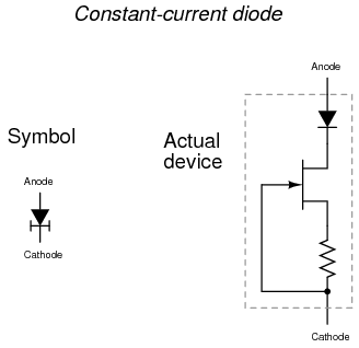
I have spent a day or two looking for a final solution and found something
I honestly didn't know existed. Although they seem rare, there are so
called current limiting diodes (CLD) which you can pretty much put in
series with a load and they'll limit the current trough it and keep is
stable as voltage changes across them.
https://sub.allaboutcircuits.com/images/05269.png

https://www.centralsemi.com/PDFs/selection/leaded/CLD_Standard.pdf

I wonder if choosing an appropriately rated one (current limit) for each
cathode and placing it between the cathode and the HV chip would provide a
nice constant current sinking scheme with a reduced component count? They
also seem to specify peak operating voltage @ 100V (I guess this is the
maximum voltage that can be put across the device? Should be more than
enough since it would typically see cca 30-40V?), and maximum limiting
voltage (so, this should be the maximum voltage drop that the diode will
take onto itself while conducting current?)

Dana četvrtak, 23. veljače 2017. u 19:21:36 UTC+1, korisnik gregebert
napisao je:
>
> That's the driver topology I use, except I omit the zener diode (good
> idea, though, for NMOS) and the base resistor because I dont see a hazard
> without them. If there is a power-on transient that occurs when the HV
> supply is energized (very unlikely, because the HV DC filter cap would need
> to be missing/open) , it would be a positive voltage-spike and the worst it
> could do is cause the driver NPN to turn-on briefly. More-likely, any
> leakage from collector-to-base would bleed-away thru the ESD network on the
> driving logic; the charge would be very small, perhaps negligible, because
> it would be whatever leaked from the collector of the driver NPN to the
> base (this is a reverse-biased junction). Regardless, there still is
> current-limiting because of the emitter resistor.
>
> I'm not aware of any mechanism that would cause a current-spike thru the
> tube at turn-on. When the logic goes to '1', the transistor will turn on
> rapidly, and it may actually saturate because the tube itself requires
> several microseconds to ionize. During this time the base-current will be
> at it's maximum (the target tube current). As the tube ionizes, it's
> current will go thru the transistor and the negative feedback at the
> emitter will gradually reduce the base-current from the logic. There's
> definitely a current-spike from the driving logic as the tube stabilizes,
> but it's only a few mA. You could add a series base-resistor to reduce the
> peak base-current, but if you check the datasheet for the transistor it's
> very likely the max base-current spec is much higher, making the resistor
> unnecessary. Unless I'm really missing something, I dont see where current
> thru the tube will spike at turnon or turnoff.
>
> As far as a current-spike at tube turnon/turnoff, yes there will be some
> Ldi/dt and 1/2LI^2 effects, but they will be small because we're dealing
> with milliamps. For example, if you are switching 5mA off in 10nsec, and
> there is 1uH of wiring inductance, the voltage spike (Ldi/dt) is 0.5 volts.
> [ Imagine if this was a motor controller with a 50 amp load.....ouch!...
> but there are circuit techniques to deal with that ].
>

--
You received this message because you are subscribed to the Google Groups
"neonixie-l" group.
To unsubscribe from this group and stop receiving emails from it, send an email
to [email protected].
To post to this group, send an email to [email protected].
To view this discussion on the web, visit
https://groups.google.com/d/msgid/neonixie-l/c9fa8047-3049-49a5-b2a7-1bba3d0181f6%40googlegroups.com.
For more options, visit https://groups.google.com/d/optout.