I think the "resistor network" and finite element approaches discussed
below are a great track for understanding the possible magnitude of the
Tout error.  The big uncertainty is the pipe thread.  It may take
experiments to estimate the thermal resistance across the pipe thread -
particularly if it is NPT instead of NPTF because NPT will require
Teflon tape to seal which would provide greater thermal isolation of the
outlet pipe.
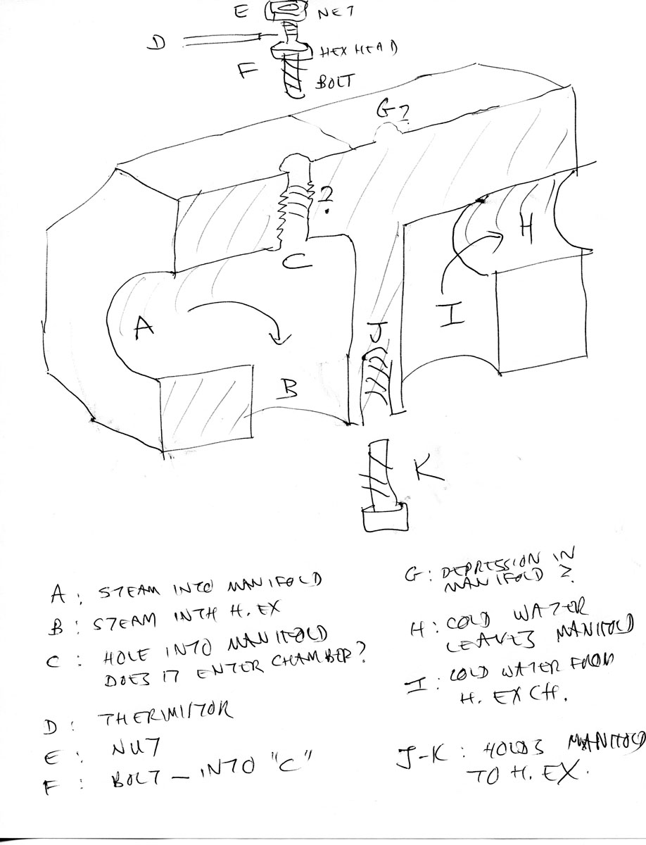
Can anyone discern the thread type or whether Teflon tape has been used?

Bob Higgins

-----Original Message-----
From: Alan J Fletcher [mailto:[email protected]]
Sent: Thursday, October 13, 2011 7:20 PM
To: [email protected]
Subject: RE: [Vo]:Analysis by Bob Higgins

At 03:26 PM 10/13/2011, Higgins Bob-CBH003 wrote:
>Hi Mark,
>
>I will consider such a drawing.  However, the present diagram is not
>geometrically correct - the internal unit is rotated in the
>cross-section so as to highlight the fins.  What is needed is a proper
>drawing from the pictures.  I just don't know what useful insight would
>be obtained from spending the time on that.

I don't think anything's to gain.   The only thing I'd change is to
mark the pressure regulator as speculative.

>I think it would be more useful to draw a speculative cross-section of
>the headers of the heat exchanger to have a proper discussion of the
>heat flow.  It is my contention, that because of the high secondary
>flow, that the heat from even primary hot water would not cause a
>significant error temperature rise in Tout.  This is because the heat
>conducted through the brass from the primary input would have to travel
>along the brass shell past the flowing secondary water for at least an
>inch through a cross-section of about 1/4".  The secondary water tube
in
>that section can be considered nearly a perfect sink because of the
high
>flow, and almost all of the heat from the primary will terminate in
that
>water - which is where it is supposed to terminate anyway.

I started on that : http://lenr.qumbu.com/111010_manifold_001_h1200.jpg
(but misunderstood the "nut" that my observer said the thermocouple
was connected to -- so I didn't draw the attached pipe segments).

See (eg) my 2-resistor models at
http://www.mail-archive.com/[email protected]/msg52539.html
(Horace Heffner first suggested the resistor model, but I used it in
a different way).

21-resistor model
http://www.mail-archive.com/[email protected]/msg52547.html

He gave me some clear pictures of the manifold :
http://lenr.qumbu.com/111010_pics/111010_1_crop.jpg
http://lenr.qumbu.com/111010_pics/111010_2_crop.jpg
http://lenr.qumbu.com/111010_pics/111010_3_crop.jpg
http://lenr.qumbu.com/111010_pics/111010_4_crop.jpg


>Regards, Bob Higgins


-----
No virus found in this message.
Checked by AVG - www.avg.com
Version: 10.0.1411 / Virus Database: 1522/3949 - Release Date: 10/13/11