I put the answers in your message

23/08/2017 20:22, Brent Hilpert via cctalk wrote:
Am I correct in inferring that this machine (the processor) has four +5V
regulators?:  it appears there are 2 power supply chassis (rear photo), each
with 2 regulators,
or are those 2 chassis not identical and there are only to two +5 regulators?
I myself have trouble understanding and for good reason:

The power supply Gl provides :

   - unregulated +15V
   - unregulated -15V
   - regulated -5V
   - regulated +15V
   - regulated +5V voltages
   - a 30V peak-to peak voltage
   - a time delayed (sequenced) outputs; MEM OK, +5V OK and Power Fail
The sequenced outputs are such that upon power turn-on, first the +5V OK
occurs, then MEM OK, followed by Power Fail. Upon power turn-off or when
input power is lost, first the Power Fail goes low, then MEM OK and then
+5V OK goes down.
The G2 type Power Supply provides :

   - unregulated +15V
   - unregulated -15V
   - two distinct regulated +5V
   - regulated -5V
   - a 30V peak-to-peak voltage
   - a time delayed Power Fail and +5V OK signals
Either way, is it documented or has it been mapped out how the regulators are
distributed to the bus/backplane slots?
No
If not, I would suggest doing so to start with, so you know what slots & boards
each regulator is supplying power to.
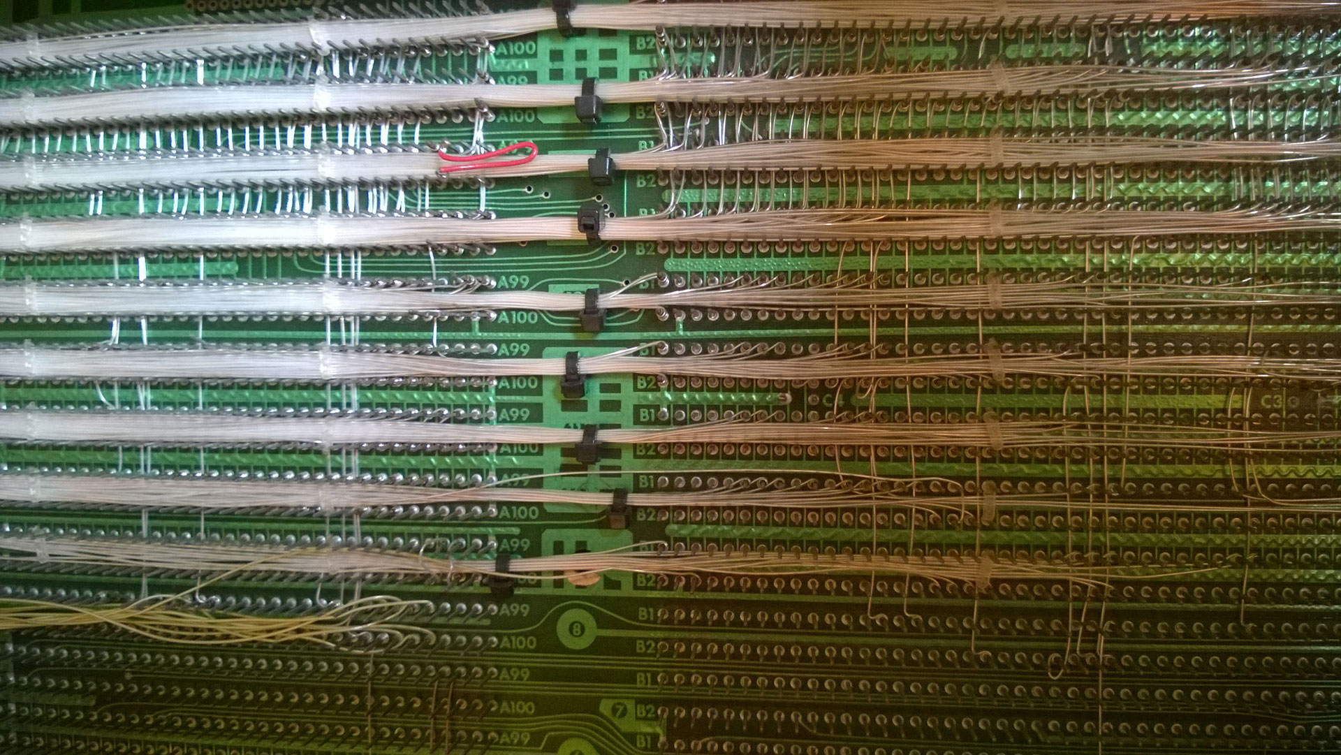
I would like to but ... here is the back-plane:

http://www.zeltrax.com/classiccmp_forum/psu_g2_test/backplane.jpg
Two possibilities come to mind:
        - One board, perhaps the CPU board from what you describe, has a fault
increasing it's current draw.
         Without other boards plugged in on the same regulator, it's within the
current capabilities of the regulator and 'appears' fine.
        But with another board, the current draw is excessive for the regulator
and current limiting kicks in.
Possible, but these 3 boards, controller for tape, disk pack, scanner
(terminal), seem to be more greedy than the others (bad decoupling
capacitors ?)
        - How is the backplane for this machine organised: as a pure bus, or
with dedicated slots for specific boards?
Dedicated slots for specific boards
Even if it is a bus structure, there might be requirements/limits on board
combinations to distribute the load amongst the regulators.
Might the machine have been misconfigured by someone moving boards around, so
that 2 heavy load boards end up on the same regulator and send it into current
limiting?
Unlikely, the stickers on the chassis indicate the location of the
boards, this seems to be like that since factory.
A minor comment regarding the components in the power supply: Q13 is a stage in
the regulator drivers and as consequential as other components such as Q2.
Do you think that Q12 (linked to defective A1 / + 5v) could be the culprit?