Hi all,
Thank you Marc, I will follow your advice. Doubts must be removed. I
would be glad to know that the big (and expensive) capacitors are OK.
In the meantime I have new information. Following the remarks of Brent
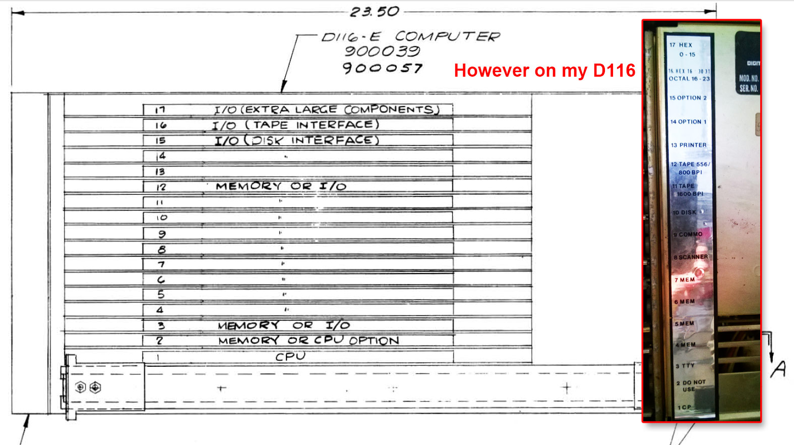
Hilpert I sought to have more information on the backplane of my D116-E.
I always assumed that the information in the manuals did not match my
version of backplane because of this:
http://www.zeltrax.com/classiccmp_forum/backplane/01.jpg
The boards are placed to another slots in the documentation. I put this
on the accounts of the many revisions but also the fact that the
computer has been distributed by Nixdorf and they probably assembled the
elements, and made the setup of the backplane with the wires. Regardless
of the configuration of the slots, the wires setup, the associated
external connectors, at the level of power supply finally I thinks that
should be the same situation on my D116 as on another.
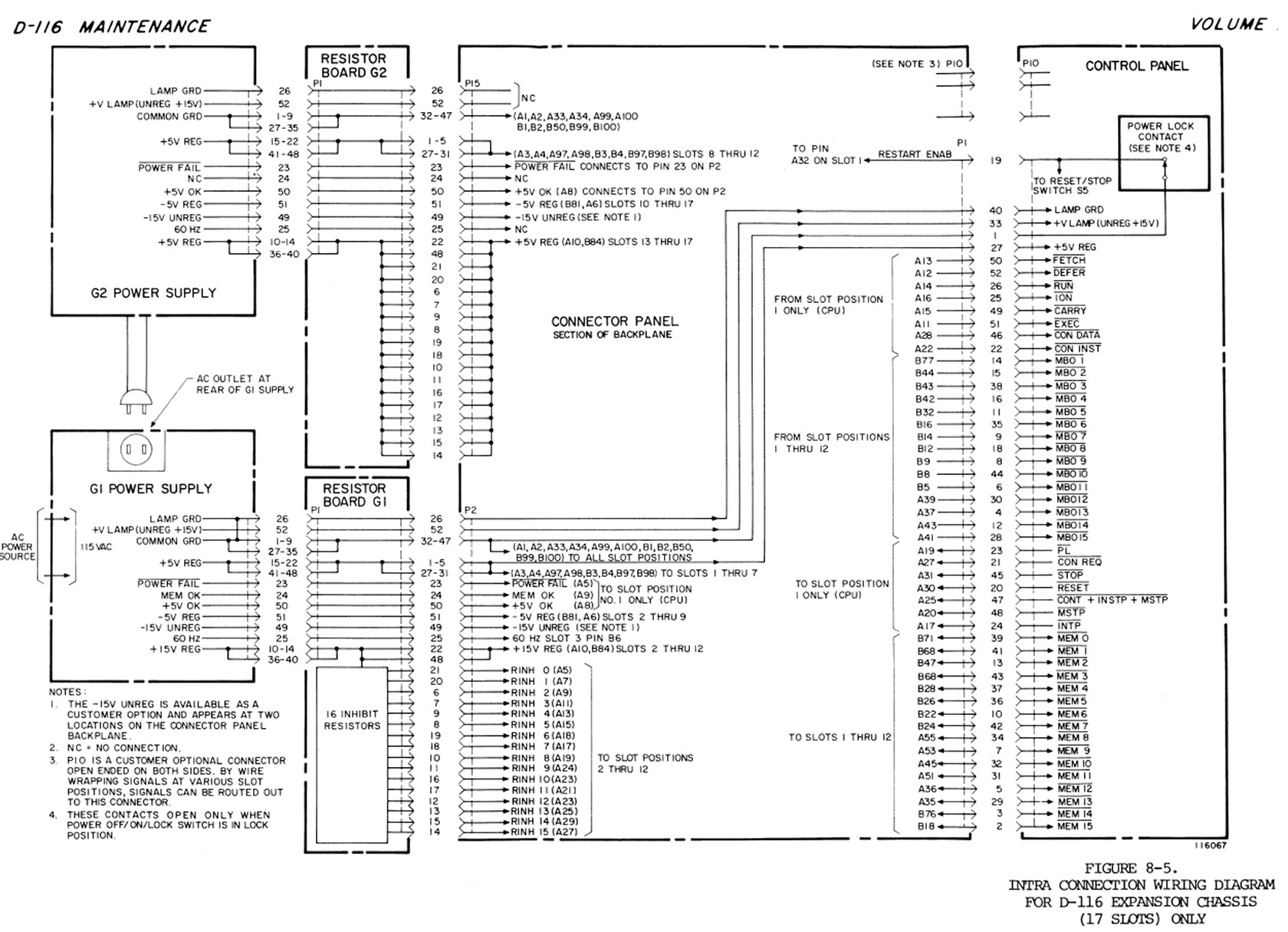
In digging into the second manual which does not contain the schematics
I found this precious diagram:
http://www.zeltrax.com/classiccmp_forum/backplane/diagram.jpg
I discovered that the common point that brings together the boards
causing the Power Fail (HDD controller / Tape controller / Scanner) is
the fact that they are in the slots from 8 to 12 which are powered by
the regulated +5V of the circuit A2.
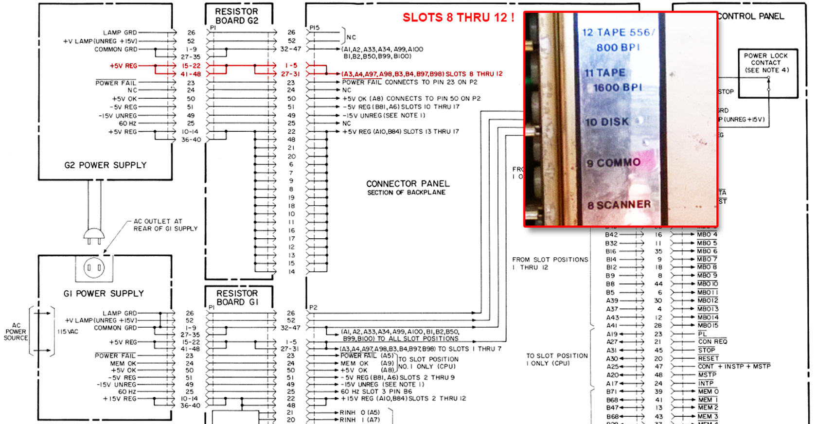
http://www.zeltrax.com/classiccmp_forum/backplane/diagram2.jpg
In other words, the circuit + 5V A2 of the power supply G2 serves only
to power the boards in the slots from 8 to 12 which cause a power fail
if only one of these slots is populated with one of the boards.
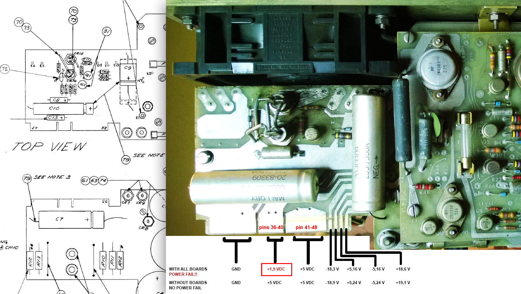
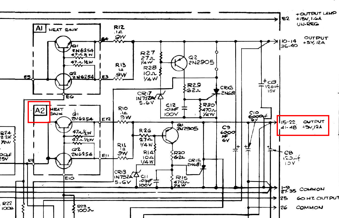
What I don't understood yet is why it's on the pins of A1 (10-14 /
36-40) that I measure a drop of tension?
http://www.zeltrax.com/classiccmp_forum/backplane/pins_a1.jpg

Because A2 is on the pins 15-22 / 41-48
http://www.zeltrax.com/classiccmp_forum/backplane/diagram_a2.jpg
I will re-read the operation of the Power Fail, maybe it supposed to
clamp A1 even in case of problem on A2 ?
Or I don't understood all the intricacies about the power supply of
these antique boards ^^
Anyway I'll do the tests you suggest Marc, it sounds good to have
confirmation that the basic level are working well before going any further.
Thank you for your help ;-)

Dominique
(PS: Sorry for duplicate messages, I had to go wrong with the reply
addresses so that it appears on the forum)
On 25/08/2017 06:43, Curious Marc wrote:
Dominique,
I wouldn't worry about the readings on your 0.1 Ohm resistor, you are
not going to get any trustable results on something that low without
a four wire ohm-meter.
It seems that you have eliminated the power transistors as being the
source of the failure.
I'd like to eliminate the rectifier diodes or the big caps as the
source of the problem
1- Could you please measure and compare (or better get a scope trace)
of the voltage at the F3 and F2 fuses when the voltage drops. If the
voltage also drops at the fuse (pre-regulation) then either your
caps/diode combo is not good, or your boards are drawing too much
current.
2-If that's the case, you could also easily swap the power source for
the two regulators. Temporarily lifting both fuses on the output side
, and cross wire F2 to feed A2 and F3 to feed A1. If the fault moves,
that would strongly indicate that one of the cap/diode combo is bad.
If it does not, then either the regulation circuitry is bad or the
boards draw an anomalous amount of power.
3-Measure how much each board is pulling (as far as amps). You can do
this easily by removing the fuse and putting an ammeter in its place,
then plug each board one at a time, and read what the amperage is.
4-Do a similar measurement adding boards one by one and see at which
amperage the voltage starts to degrade, and if it exceeds the design
criterion for the power supply.
Marc
Here is the situation.
The + 5V 12A that collapses comes out from pins 10-14 / 36-40, the other
+ 5V 12A (pins 15-22 / 36-40) never goes down.
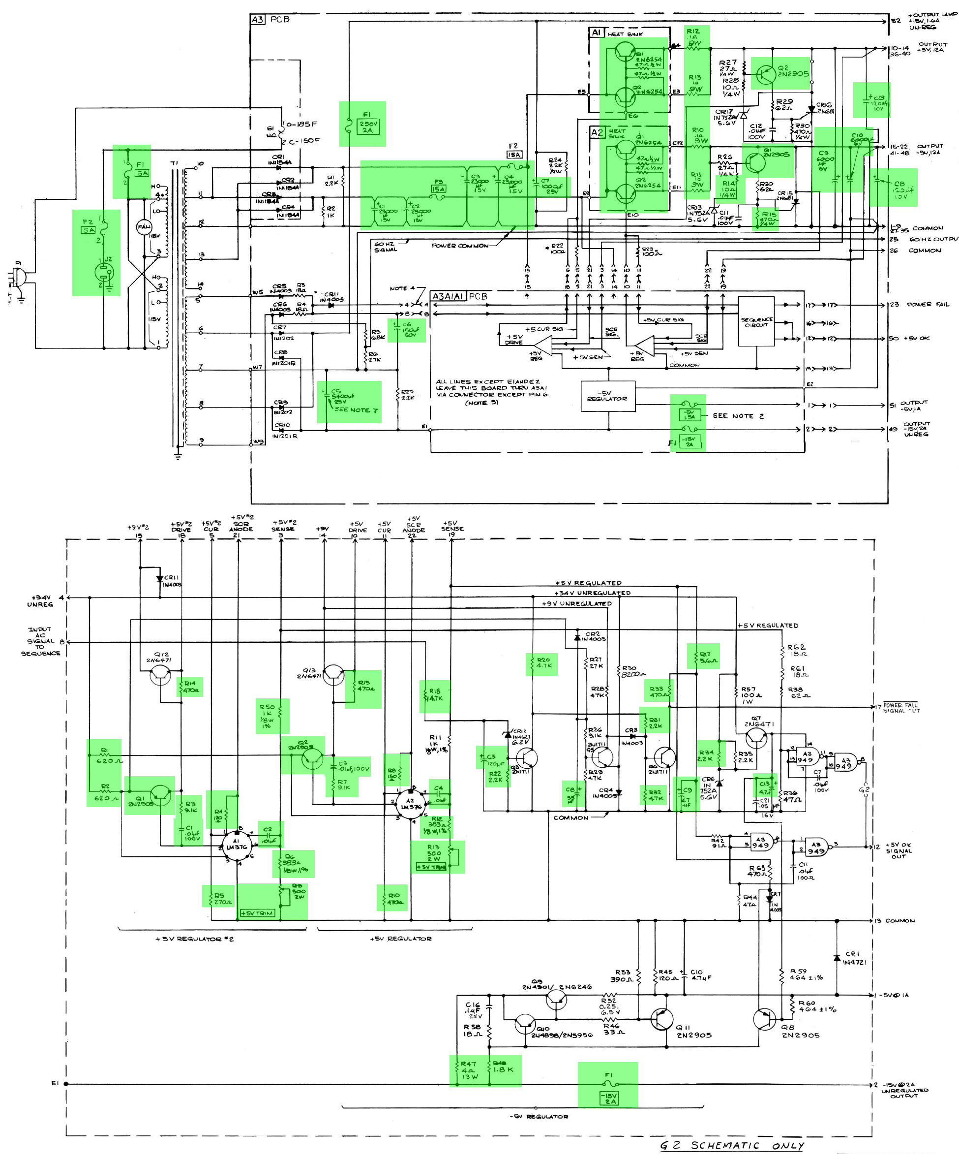
All that I surrounded in green on that image (1950×2361, zoomable) are
the components that I tested on the power supply G2, A3 motherboard,
regulation board and heatsink A1 + A2:
http://www.zeltrax.com/classiccmp_forum/psu_g2_test/g2_tested_components.jpg
To eliminate some doubts and because I do not have some spare parts on
hand, I switched the modules A1 and A2, same result. Idem with the
transistors 2N2905, same result.
The result is always the same : it's always the +5V on pins 10-14 /
36-40 that collapses, never the other output.
Some resistors are not yet tested is because these must be de-soldered
for a valid test, but the printed circuit is very fragile and many
component have legs bent into the weld.
Except for the not tested components (among others the LM376, the
rectifier diodes) At this stage I start again to suspect a little
everything. The famous large capacitors of the power supply (C1 to C4).
But also a possible problems on the boards of the computer itself.
As one of you mentioned, the hypothesis of shorted decoupling capacitors
on the boards could put the power supply in default.
Note that the machine runs normally with the CPU board, three core
memory boards (400w each) + two multiplexing boards for terminals + the
printer board.
If I add only one of these remaining board:
- Disk Pack Controller
- 9-track tape Controller
- "scanner" board (also for terminals)
-> Power Fail.
Note that : if I only connect the CPU and the disk pack controller card:
Power Fail too !!
What makes me doubtful about this scenario is that I can not imagine
that these three boards, each causing the Power Fail, could fail
simultaneously. Remember that the first time I powered up the beast (one
big hour), the machine was working with all the boards and Power Fail
appeared at once.
I have not retested since but also note that by adding an external power
supply just for the deficient + 5V , the machine has restarted and even
booted the operating system.
If you have another ideas? LM376?
Thanks
Dominique