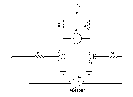
I tried the circuit with the following values: R4=R3=22k ohm and
R1=R2=220k ohm  Q1=MPSA42 and Q2=MPSA92 HV= 180 VDC TP1=5 VDC
Only half of it worked (one electrode lights).  If I only use MPSA42
that part of the circuit works fine (made a test circuit with only the
NE-2, a transistor and the required resistors).  If I replace put the
MPSA92 in, the NE-2 stays on, no matter if the 0V or 5V is applied to
the base.  I've tried 2 MPSA92's fresh from the package and still no
luck.  What am I missing?


On Jan 10, 7:29 am, John Rehwinkel <[email protected]> wrote:
> >>http://www.vitriol.com/images/tech/ne2both.gif
>
> >> High input lights one side, low lights the other side, a square wave
> >> oscillates between them.  At one hertz, this makes a nice colon indicator,
> >> hopping back and forth visibly between the electrodes.  At a hundred hertz
> >> or higher, both appear to be lit.  You can use a transistor as the
> >> inverter, or drive both transistors directly from microcontroller I/O pins
> >> - if you do it that way, if you turn both transistors on or off at the
> >> same time, the light will go out.  If one is on and one is off, you light
> >> one electrode.
> > I like that, thanks!
>
> > Should also work with a 555 since it will source and sink?
>
> Should work just dandy with a 555.
>
> - John

--
You received this message because you are subscribed to the Google Groups
"neonixie-l" group.
To post to this group, send an email to [email protected].
To unsubscribe from this group, send email to
[email protected].
For more options, visit this group at
http://groups.google.com/group/neonixie-l?hl=en-GB.